Implementing High-Efficiency Power Rails in Next-Gen Microelectronics
Power integrity has become the bottleneck for system reliability. How advanced substrates and smarter regulation are changing power delivery design.
By YDT EditorialUpdated 3 min read
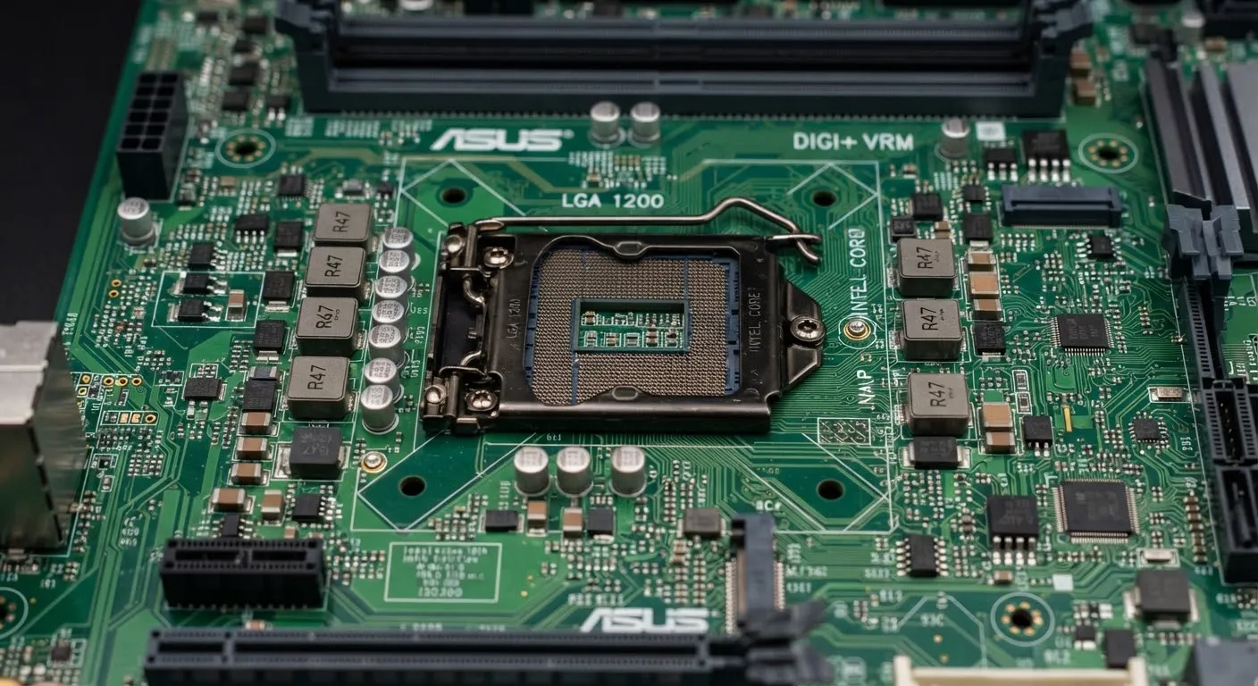
As we push the boundaries of miniaturization, the management of power integrity in high-performance computing environments has become the primary bottleneck for system reliability. This analysis explores the shift from traditional copper planes to advanced composite substrates for thermal management.
The transition to 3nm-class nodes requires a significant reduction in transient voltage spikes to maintain logic gate stability. Conventional LDO regulators struggle to meet sub-millivolt tolerances under bursty, AI-style load profiles, pushing designers toward integrated voltage regulation and smarter telemetry loops.
Material specifications compared
The substrate sets the ceiling for everything else in the power delivery network. Here is how the incumbent stacks up against the polyimide composites entering volume production:
Substrate comparison
- Dielectric constant
- FR4: 4.4 — Polyimide: 3.2
- Thermal conductivity
- FR4: 0.25 W/m·K — Polyimide: 0.52 W/m·K
- Max operating temp
- FR4: 130 °C — Polyimide: 240 °C
- Relative cost
- FR4: 1× — Polyimide: 3–4×
The dielectric improvement matters twice: lower loss at high switching frequencies, and better impedance control for the fine-pitch routing that dense VRM phases demand. The thermal budget is what unlocks placing regulation physically closer to the load.
Modeling rail stability
A simple way to reason about transient behavior is to measure how long a rail stays outside its tolerance window after a load step:
def calculate_rail_stability(voltage_log, threshold=0.005):
    """Transient recovery time for a power rail under heavy I/O load."""
    transients = [v for v in voltage_log if abs(1.2 - v) > threshold]

    if not transients:
        return 0.0  # nominal stability achieved

return len(transients) * SAMPLE_RATE_MSDirect die cooling: the trade-offs
Pros
- Eliminates the thermal interface material — the dominant resistance in the stack
- Cuts delta-T under peak load, enabling higher sustained clocks
- Shrinks the guard-band needed for thermal throttling
Cons
- Real risk of mechanical fracture during mounting
- Coolant sealing requirements add cost and failure modes
- Warranties rarely survive the modification
The technique remains most viable where reliability budgets are engineered end-to-end — data center and aerospace applications rather than consumer hardware.
Verdict
Power delivery is no longer a supporting subsystem; it is a first-class design constraint that shapes floorplans, substrate choices, and cooling strategy. Teams that treat the power delivery network as an afterthought will find their timing closure eaten by guard-banding against noise they could have engineered out.
FAQ
Does this approach apply to consumer-grade hardware?
Primarily no. The cost of polyimide substrates and precise VRM tuning makes this most viable for data-center and aerospace applications, where reliability requirements override initial bill-of-materials cost.
What is the expected lifespan of these power rails?
Under continuous 24/7 industrial load, projected MTBF is approximately 85,000 hours assuming standard ambient cooling — roughly double a conventional FR4-based design under the same profile.
Is backside power delivery related to this?
It is complementary. Backside power delivery addresses on-die distribution, while substrate and VRM design govern how cleanly power reaches the package in the first place. Both attack the same transient budget.
Filed under
Related articles
Hardware29 min read
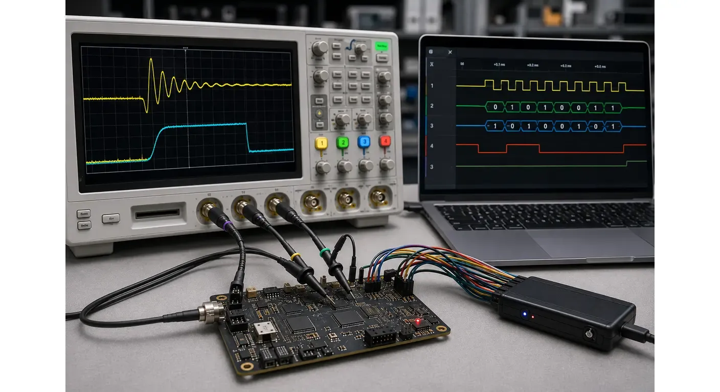
Oscilloscope vs Logic Analyzer: Key Differences and How to Choose
Oscilloscope vs logic analyzer: how each instrument measures signals, where each one fails, and how to choose the right tool for analog, digital and mixed-signal debugging.
Hardware2 min read
The Future of RISC-V: Decentralizing the Silicon Monopoly
Open-source hardware is gaining real traction in enterprise data centers. A look at the technical hurdles and strategic implications of the RISC-V movement.
Hardware2 min read
ARM Architecture's New Frontier: The 2nm Challenge
The engineering hurdles facing the next generation of mobile and server processors as manufacturing approaches physical limits.
Electronics18 min read
Function Generator vs Arbitrary Waveform Generator: What You Are Buying
Three names, two architectures: how DDS and point-by-point playback differ, what the labels hide, and how to read the architecture off a datasheet.