Electronics18 min read
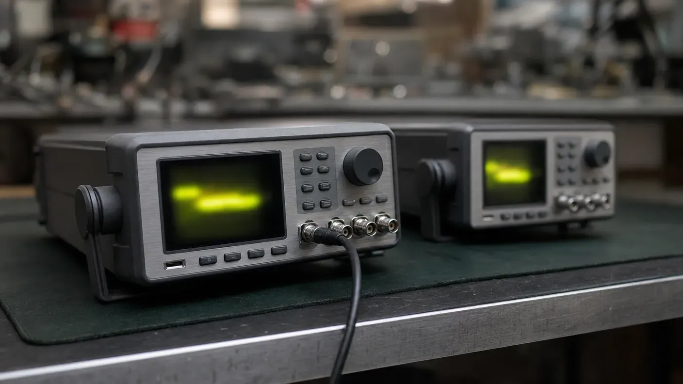
Function Generator vs Arbitrary Waveform Generator: What You Are Buying
Three names, two architectures: how DDS and point-by-point playback differ, what the labels hide, and how to read the architecture off a datasheet.
A complete guide to electronic test and measurement — oscilloscopes, multimeters, spectrum analyzers, how to choose instruments, CAT safety ratings, and measurement best practices.
By YDT EditorialUpdated 21 min read
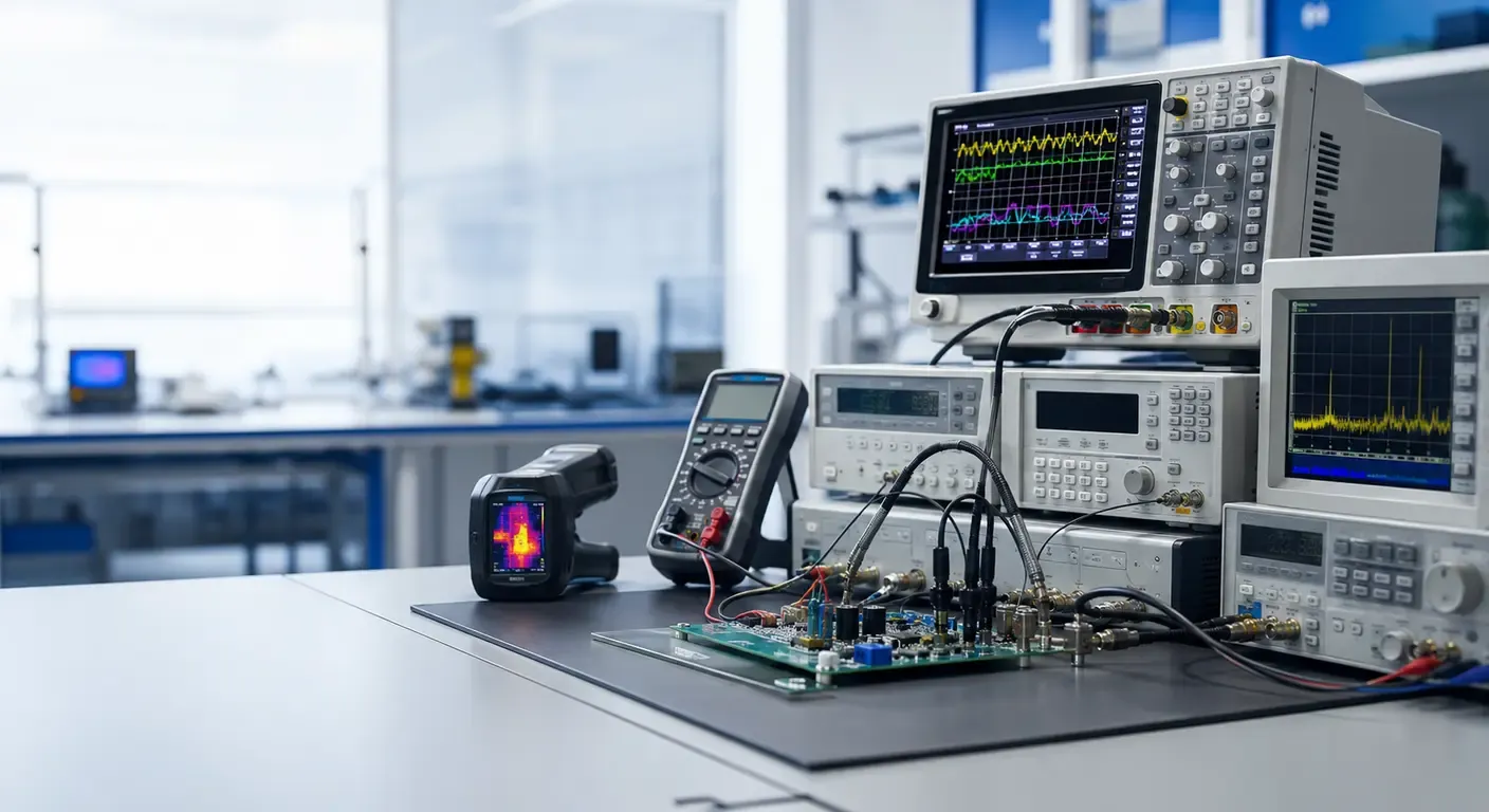
Test and measurement (T&M) is the engineering discipline concerned with quantifying electrical, physical, and environmental parameters to verify that circuits, components, and systems meet their design specifications. Without reliable T&M, every stage of electronics development — from prototype validation to production-line quality control — operates on assumptions rather than data.
This guide covers the core categories of electronic test equipment, explains the specifications that matter when selecting instruments, and outlines best practices for accurate, repeatable measurements. It also introduces supporting resources — calculators, comparison guides, and instrument-specific buying guides — that form the broader Test & Measurement knowledge base on this site.
Test and measurement refers to the process of applying known stimuli to a device under test (DUT) or observing its behavior under operating conditions, then capturing quantitative data to compare against expected values or tolerances. “Test” typically implies a pass/fail determination — does the output meet spec? “Measurement” focuses on the value itself — what exactly is the output?
In practice, the two overlap constantly. A bench engineer probing a voltage rail is both measuring the DC level and testing whether it falls within the regulator’s specified tolerance. The distinction matters more in formal quality systems (ISO 17025, for instance) where measurement uncertainty budgets are maintained separately from functional test procedures.
Inaccurate measurements propagate through the entire design cycle. A multimeter with a 2% basic DC accuracy reading a 3.3 V rail could report anything between 3.234 V and 3.366 V. If the downstream ADC reference voltage was set based on that reading, the resulting system error compounds silently.
Accuracy matters for three practical reasons:
The table below summarizes each instrument category, its measurement domain, and where it fits in a typical workflow:
| Instrument | Measures | Primary Domain | Typical Use Case |
|---|---|---|---|
| Oscilloscope | Voltage vs. time | Time-domain analog | Signal integrity, timing, transient analysis |
| Digital Multimeter | V, A, Ω, and more | DC / low-frequency AC | Component-level verification, field service |
| Logic Analyzer | Digital bus states | Time-domain digital | Protocol debugging, state machine validation |
| Signal Generator | — (stimulus source) | Waveform output | Stimulus-response testing, receiver characterization |
| Spectrum Analyzer | Amplitude vs. frequency | Frequency-domain | EMC pre-compliance, RF design, harmonic analysis |
| Bench Power Supply | — (power source) | DC supply | DUT power, load regulation testing |
| Electronic Load | — (current sink) | DC loading | Power supply validation, battery testing |
| Thermal Camera | Surface temperature | Thermal / IR | Hot spot detection, thermal design verification |
| Clamp Meter | Current (non-contact) | AC / DC current | High-current industrial measurement |
| Network Tester | Cable / link parameters | Physical layer | Cabling certification, fault location |
When to use: Any circuit where voltage varies with time — debugging waveforms, measuring rise times, decoding serial buses, or hunting transients. New to the instrument? Our guide to what an oscilloscope is and how it works covers the fundamentals first.
Modern digital storage oscilloscopes (DSOs) capture voltage waveforms, measure rise times, decode serial protocols (SPI, I2C, UART, CAN), and perform FFT analysis. Key specifications include analog bandwidth, sample rate, memory depth, and number of channels.
A 100 MHz oscilloscope captures frequency content up to its -3 dB point, but faithfully reproducing fast edges typically requires 5x the fundamental frequency. Mixed-signal oscilloscopes (MSOs) add digital input channels for simultaneous analog and digital capture. Major manufacturers include Tektronix, Keysight, Rohde & Schwarz, Rigol, and Siglent.
None of that matters if the instrument captures the wrong moment. Our guide to oscilloscope triggering covers how to isolate the specific event you’re chasing rather than an arbitrary slice of the input.
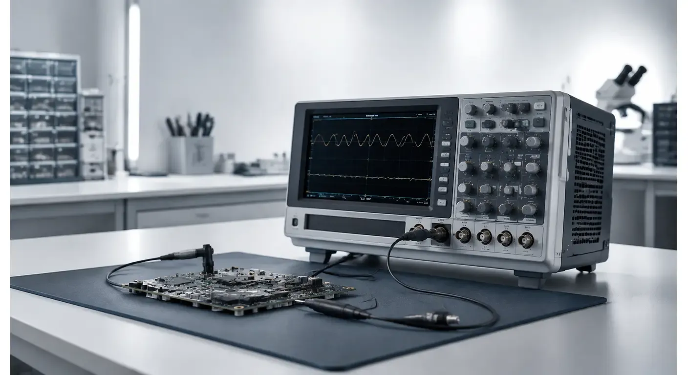
Older CRT-based analog scopes still turn up on benches and the secondhand market. Our comparison of analog and digital oscilloscopes covers where each technology still makes sense.
Choosing the right oscilloscope is one of the most impactful equipment decisions an engineer makes. Our dedicated guide to the best digital oscilloscopes covers bandwidth selection, memory depth trade-offs, and models ranked by application and budget.
When to use: DC and low-frequency AC measurements — verifying supply rails, checking continuity, measuring component values on the bench or in the field.
Bench DMMs offer 4.5, 5.5, or 6.5 digits of resolution plus functions like capacitance, frequency, and temperature. A 6.5-digit bench DMM resolves 1 µV on a 1 V range. Handheld DMMs sacrifice some resolution for portability and add CAT-rated input protection for field use.
True-RMS measurement capability is essential for non-sinusoidal AC waveforms — a common scenario with switch-mode power supplies and variable-frequency drives. Fluke dominates the handheld market; Keysight and Fluke offer the most widely deployed bench DMMs.
Choosing between them is a matter of which specification bounds your measurement, not a feature count — our guide to how a multimeter’s specifications bound the measurement works through safety category, accuracy at the actual reading, burden voltage and AC bandwidth to build a requirement profile you can check against any datasheet.
When to use: Debugging digital bus protocols, firmware-hardware interactions, or state machines where you need high channel count and deep capture rather than analog detail.
Logic analyzers capture and decode digital bus activity across 16, 32, or more channels simultaneously, displaying data as timing diagrams or decoded protocol transactions. They trade analog amplitude detail for channel count and deep memory. Saleae, Keysight, and Teledyne LeCroy offer models across the price spectrum.
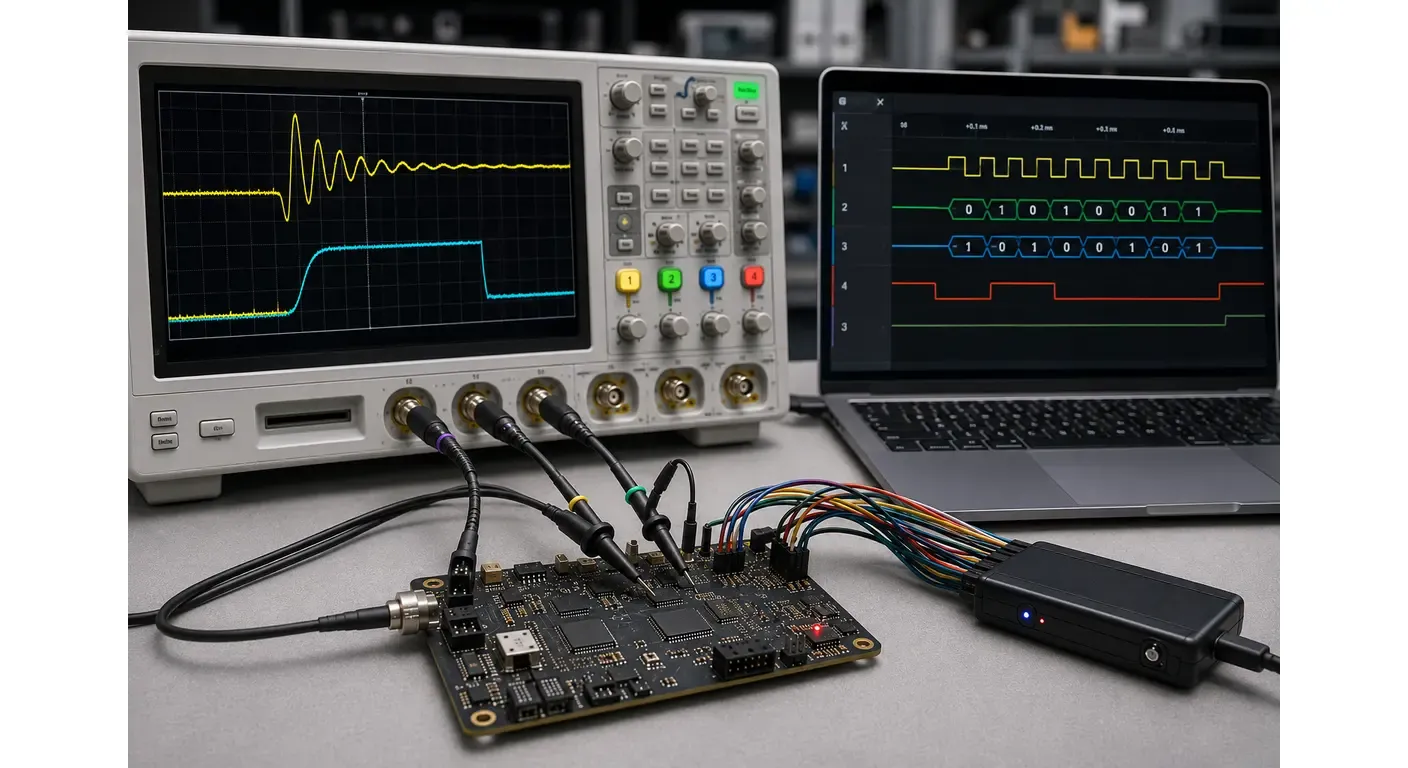
When to reach for a logic analyzer versus an oscilloscope (or MSO) is one of the most common points of confusion in digital debugging — our oscilloscope vs. logic analyzer comparison explains where each tool fits and how MSOs bridge the gap.
When to use: Characterizing a DUT’s response to known stimuli — frequency response, transient behavior, receiver sensitivity, or modulation quality.
Signal generators produce known waveforms — sine, square, pulse, arbitrary, or modulated RF carriers — to drive a DUT. Categories include:
Selecting the right signal source depends on the application: a power supply designer testing transient response needs a fast-edge pulse generator, while a communications engineer needs a vector signal generator with complex modulation. Our guide to choosing between function and arbitrary waveform generators walks through the load a bench instrument assumes, bandwidth against sample rate, and the resolution a range setting buys back — RF and vector generators are a separate family with their own specification vocabulary.
When to use: Any measurement in the frequency domain — EMC pre-compliance, spurious emission hunting, phase noise characterization, or RF transmitter verification.
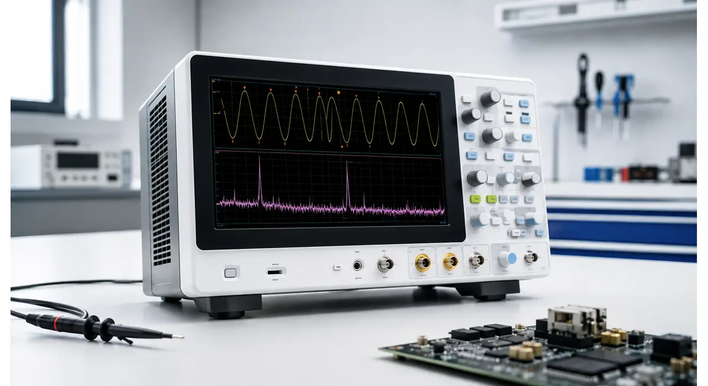
A spectrum analyzer displays signal amplitude as a function of frequency, complementing the oscilloscope’s time-domain view. Spectrum analyzers are essential for EMC pre-compliance, RF design, spurious emission hunting, and characterizing phase noise or harmonics.
Swept-tuned analyzers offer wide dynamic range. Real-time spectrum analyzers (RTSAs) capture transient or frequency-hopping signals that swept analyzers miss. Near-field probes extend their use to PCB-level radiated emission debugging. Rohde & Schwarz, Keysight, and Rigol are the most common names in this space. The spectrum analyzer explained guide covers architecture differences, dynamic range trade-offs, and practical EMC pre-compliance setups.
When to use: Powering prototypes and DUTs with clean, adjustable DC — especially when you need current limiting, remote sense, or programmable output sequencing.
Linear-regulated supplies offer low output noise (often below 1 mV RMS ripple) and fast transient response, making them preferable for sensitive analog and RF circuits. Switch-mode bench supplies deliver higher power density at the cost of higher output ripple.
Key specifications include output voltage range, current capacity, channel count, load regulation, and remote sense capability. Remote sense compensates for voltage drop in test leads — critical when sourcing high current to low-voltage DUTs. The bench power supply buying guide compares linear vs. switch-mode topologies, noise specifications, and programmability features across current models.
When to use: Validating power sources — characterizing output regulation, transient response, and thermal behavior of power supplies, batteries, solar panels, and fuel cells.
An electronic load sinks current from a power source under test. Modes include constant current (CC), constant voltage (CV), constant resistance (CR), and constant power (CP). Dynamic loading — switching between levels at controlled slew rates — tests a supply’s transient response. Key specifications include maximum power dissipation, minimum operating voltage, and current slew rate.
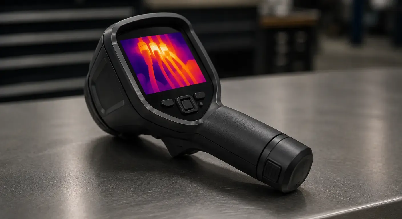
When to use: Non-contact thermal diagnosis — finding hot spots on PCBs, verifying heat sink performance, detecting failing components, or inspecting power distribution panels.
Infrared (IR) thermal cameras visualize surface temperature distribution without contact. Thermal resolution (NETD), spatial resolution (IFOV), and temperature range determine a camera’s suitability.
A thermal camera reveals a shorted decoupling capacitor, an undersized trace, or a MOSFET outside its safe operating area (SOA) far faster than point-contact thermocouples. FLIR (Teledyne), Fluke, and Hioki are prominent manufacturers. The thermal camera guide covers NETD, IFOV, temperature range trade-offs, and application-specific recommendations.
When to use: Measuring current without breaking the circuit — motor drives, distribution panels, bus bars, or any high-current path where inserting a series shunt is impractical or unsafe.
Clamp meters sense the magnetic field around a conductor, eliminating the need to break the circuit. AC clamp meters use current transformer (CT) jaws; DC-capable models use Hall effect sensors. They range from basic handheld units to bench-grade current clamps that feed into oscilloscopes or data loggers. Fluke and Hioki dominate this market.
The clamp meter guide covers AC vs. DC sensing technologies, jaw sizes, accuracy classes, and industrial application considerations.
When to use: Certifying, troubleshooting, or fault-locating copper and fiber cabling infrastructure.
Network testers encompass a broad category: cable certifiers, TDR (time-domain reflectometer) analyzers, Ethernet testers, and fiber-optic OTDRs. In electronics manufacturing and facility maintenance, they verify cabling infrastructure against standards (TIA-568, ISO 11801) and diagnose faults like impedance mismatches, opens, shorts, and excessive attenuation.
Accuracy describes how closely a measured value represents the true value. It is typically expressed as a percentage of reading plus a percentage of range (e.g., ±0.05% of reading + 0.02% of range). Always compare accuracy specifications at the range and conditions relevant to your measurement — published specs at 23°C ± 5°C may degrade significantly outside that window.
Resolution is the smallest change a measurement can detect. A 12-bit ADC digitizing a 0–10 V range resolves approximately 2.44 mV per step. Higher resolution does not guarantee higher accuracy — they are independent specifications. A 6.5-digit DMM resolves 1 µV on a 1 V range, but its accuracy still depends on calibration and operating conditions.
For oscilloscopes, analog bandwidth is the -3 dB point — the frequency where displayed amplitude drops to 70.7% of the true value. Select a bandwidth at least 5x the highest frequency component you expect to measure, or 1.0x to 1.9x the signal’s knee frequency for digital signals. Both figures are margins rather than thresholds: at the rated bandwidth the display is already about 30% low, which is why choosing an oscilloscope bandwidth starts from the fastest edge in the system, not the clock frequency.
The Nyquist theorem requires a minimum sample rate of 2x the highest frequency component; in practice, 5x to 10x oversampling produces reliable waveform reconstruction. Some oscilloscope architectures halve the per-channel rate when multiple channels are active — verify this in the datasheet. Our guide to oscilloscope sample rate covers how memory depth and channel interleaving interact with that headroom in practice.
Four analog channels is standard for embedded work; two suffice for basic power supply debugging. MSOs add 8 or 16 digital channels. Consider whether differential measurements (requiring two channels per signal) will demand additional analog inputs.
IEC 61010-1 defines measurement categories (CAT I through CAT IV) based on the prospective fault energy of the circuit under test:
| Category | Environment | Example Locations | Fault Energy |
|---|---|---|---|
| CAT I | Protected electronic equipment | Signal-level circuits, bench electronics | Lowest |
| CAT II | Receptacle-connected loads | Appliances, portable tools, wall outlets | Moderate |
| CAT III | Distribution-level, fixed installation | Panel boards, bus bars, feeders, motor circuits | High |
| CAT IV | Origin of installation, utility-level | Service entrance, primary overhead/underground supply | Highest |
Higher CAT numbers indicate higher fault energy and require more robust input protection. Never use a CAT II-rated meter in a CAT III environment. The instrument’s CAT rating and voltage rating together determine its safe application — a CAT III 600 V meter is not equivalent to a CAT II 1000 V meter.
Accredited calibration (ISO/IEC 17025) provides a certificate with measurement uncertainties traceable to national standards. Factory calibration is adequate for development work, but production test and regulatory applications typically require accredited calibration. Establish intervals based on manufacturer recommendation, usage intensity, and historical drift data.
T&M in PCB design spans signal integrity validation (impedance measurements, eye diagrams, return loss), power distribution network (PDN) analysis, and thermal profiling. High-bandwidth oscilloscopes and vector network analyzers (VNAs) verify that controlled-impedance traces meet target impedances. Thermal cameras validate heat dissipation paths and copper pour adequacy.
Debugging embedded systems demands simultaneous analog and digital visibility. MSOs decode SPI, I2C, and UART traffic while displaying supply rail transients. Logic analyzers capture bus-level protocol exchanges over millions of clock cycles. Current probes on supply pins reveal firmware-dependent power consumption patterns critical for battery-powered designs.
Industrial environments require CAT III or CAT IV-rated instruments. Clamp meters monitor motor currents, thermal cameras detect failing contactors or overloaded wiring, and handheld oscilloscopes troubleshoot noisy sensor signals on long cable runs. Process calibrators source and measure 4–20 mA loops and thermocouple signals.
Automotive test demands wide temperature range operation, CAN/LIN/FlexRay protocol decoding, and EMC testing against CISPR 25 and ISO 11452. Power supply transient testing per ISO 16750 (load dump, cold crank) requires programmable sources and electronic loads capable of generating specified waveform profiles.
Aerospace electronics operate under stringent reliability and environmental requirements (DO-160, MIL-STD-810). T&M in aerospace emphasizes traceability, calibration discipline (often with ANSI/NCSL Z540.3 compliance), and environmental stress screening. High-altitude and radiation effects testing requires specialized chamber instrumentation.
Telecom test covers RF parameter verification (output power, spurious emissions, receiver sensitivity), modulation quality (EVM, ACLR), and baseband signal analysis. Vector signal analyzers, vector network analyzers, and BER testers form the core instrument set. Fiber-optic test (OTDR, optical power meters) supports physical-layer network verification.
Power electronics testing — characterizing switch-mode converters, inverters, motor drives, and battery management systems — requires instruments rated for high voltages and high currents. Differential probes with adequate common-mode rejection ratio (CMRR) and bandwidth, high-voltage oscilloscopes, and power analyzers measuring real power, power factor, and efficiency are standard tools.
A common starting point is 12 months for bench instruments and 6 months for production-critical equipment. Track drift over multiple calibration cycles — if an instrument consistently returns well within tolerance, extend the interval. If it drifts close to limits, shorten it.
An oscilloscope is only as good as its probe. Match the probe to the measurement — the wrong probe type introduces errors that no amount of post-processing can fix.
| Probe Type | Typical Bandwidth | Best For | Watch Out For |
|---|---|---|---|
| Passive 10:1 | Up to 200–500 MHz | General-purpose, power rails | Capacitive loading on high-Z nodes |
| Active | 1 GHz and beyond | Fast digital signals, high-Z circuits | Cost, fragility, power requirement |
| Differential | Up to 1 GHz+ | Floating measurements, high CMRR | Offset range limits, cost |
| Current (Hall-effect) | DC to ~100 MHz | Non-contact AC/DC current | Degaussing drift, minimum current |
| Current (Rogowski) | AC only, wide range | High-current AC, inrush events | No DC capability |
Match the probe bandwidth to the oscilloscope bandwidth; a 500 MHz scope with a 100 MHz probe has an effective system bandwidth around 100 MHz. Our complete oscilloscope probe guide covers attenuation, loading, compensation and safety ratings in depth.
Noise limits effective measurement resolution. Practical mitigation steps include:
Every passive oscilloscope probe requires compensation adjustment to match the input capacitance of its specific channel. An uncompensated probe distorts square-wave edges — producing overshoot or rounding — and introduces amplitude errors on AC signals. Compensate every time you move a probe to a different scope or channel: connect to the built-in calibration output (typically a 1 kHz square wave) and adjust the trimmer until the waveform shows flat tops and sharp corners. Our probe guide walks through the full procedure and shows how to recognize under- and over-compensation from the displayed waveform.
A long ground lead acts as an inductor. At 100 MHz, a 15 cm ground clip presents roughly 15 nH of inductance, which can resonate with probe tip capacitance and create ringing artifacts that do not exist in the actual circuit. Use the shortest ground connection available, preferably a spring-loaded ground tip or a dedicated ground point near the signal under test. For differential measurements, a differential probe eliminates the ground lead entirely.
Using a general-purpose DMM to measure millivolt-level thermocouple signals introduces errors from thermal EMF at the input terminals. Measuring high-frequency signals with insufficient oscilloscope bandwidth produces falsely low amplitudes and distorted waveforms. Matching instrument specifications to the measurement requirement is fundamental but frequently neglected.
Bandwidth limitations apply to every element in the signal chain. The system bandwidth follows:
1 / BW_system² = 1 / BW_scope² + 1 / BW_probe²
A 200 MHz scope with a 200 MHz probe yields a system bandwidth of approximately 141 MHz. Engineers who ignore this cascaded degradation routinely underestimate rise times and miss high-frequency signal anomalies.
Most instrument specifications are valid within 18°C to 28°C ambient. Operating outside that range degrades accuracy. Nearby switching power supplies, motors, or fluorescent lighting inject noise into sensitive measurements. Position instruments and cables away from known EMI sources and use shielded connections.
Reliable measurements start with correct calculations. Our electronics calculators provide quick, accurate results for common design tasks:
For unfamiliar terms or specification definitions encountered in datasheets and application notes, the electronics glossary serves as a quick reference across the full range of T&M terminology.
Test and measurement is the discipline of quantifying electrical and physical parameters — voltage, current, resistance, frequency, temperature, and many others — to verify that electronic circuits and systems operate within their specified tolerances.
A digital multimeter and an oscilloscope cover the majority of general electronics work. Add a bench power supply for powering prototypes and an adjustable signal source for stimulus-response testing. Beyond that, instrument selection depends on your specific domain — RF, digital, power, or field service.
Measurement determines a quantity's value. Testing compares that value against a defined criterion to produce a pass/fail verdict. In practice, most engineering workflows involve both simultaneously.
Calibration compares an instrument's readings to a traceable reference standard and documents the deviations. It quantifies measurement uncertainty at a specific point in time. Calibration does not inherently adjust the instrument — it may also involve correction to bring readings within specification.
A 12-month interval is standard for bench instruments; 6 months for production-critical equipment. The right interval depends on stability, usage intensity, environmental conditions, and accuracy requirements.
For general electronics work, the oscilloscope. It provides time-domain visualization of circuit behavior that no other single instrument can replicate. The DMM is a close second for DC and low-frequency AC measurements. Specialization shifts this answer — an RF engineer would prioritize a spectrum analyzer; a field electrician, a clamp meter.
Use calibrated instruments within their specified operating conditions. Select the correct measurement range (avoid measuring a 100 mV signal on a 1000 V range). Minimize lead length. Use averaging to reduce noise. Account for probe loading effects. Apply correction factors from the calibration certificate when measuring near the edges of the instrument's specified accuracy.
CAT (Category) ratings, defined by IEC 61010-1, classify the transient overvoltage environment of a measurement point — from CAT I (protected bench electronics) through CAT IV (utility service entrance). Higher numbers indicate greater fault energy. Always match or exceed the measurement environment's category with your instrument's rating. See the comparison table in the Safety Ratings section above for detailed examples.
The following guides expand on individual equipment categories with specification breakdowns, model comparisons, and practical recommendations:
Electronics18 min read
Three names, two architectures: how DDS and point-by-point playback differ, what the labels hide, and how to read the architecture off a datasheet.
Electronics23 min read
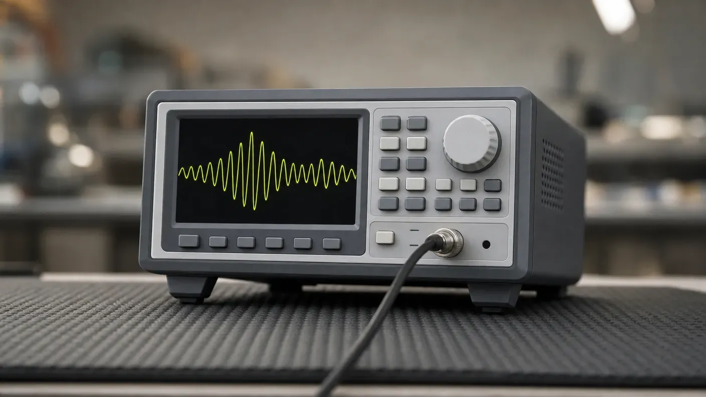
How to turn a required stimulus into datasheet requirements: the load the instrument assumes, bandwidth against sample rate, reconstruction and vertical resolution.
Electronics22 min read
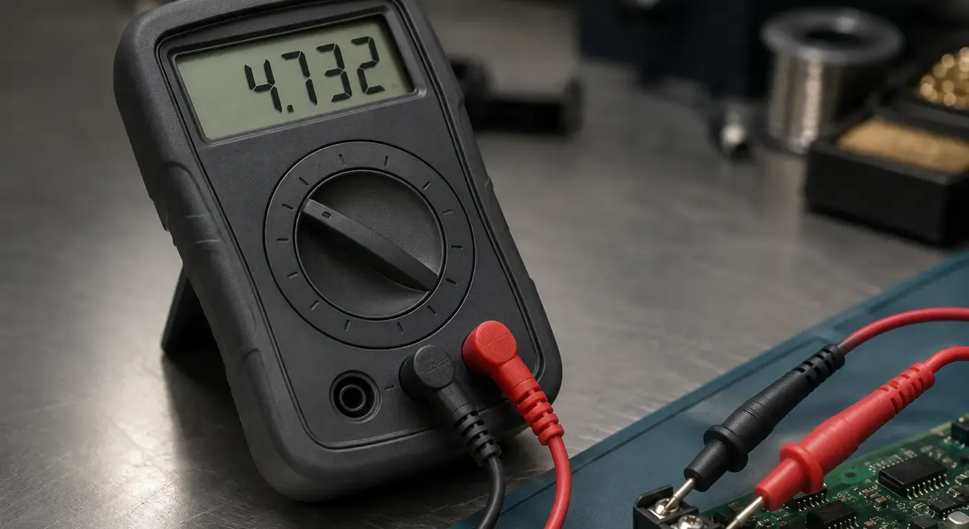
Choose a multimeter by the errors it introduces: burden voltage, input loading, AC bandwidth, safety category and accuracy on the reading you actually take.
Electronics16 min read
A thermal camera always shows a number. Learn the checks — emissivity, reflected temperature, focus and spot size — that decide whether it is a measurement.
Electronics21 min read
How an oscilloscope's FFT function works, how sample rate, record length and window functions affect the result, and how to interpret an FFT spectrum in engineering work.
Hardware29 min read
Oscilloscope vs logic analyzer: how each instrument measures signals, where each one fails, and how to choose the right tool for analog, digital and mixed-signal debugging.
Electronics17 min read
Learn the differences between analog and digital oscilloscopes, including how they work, their advantages, limitations, and the best applications for each technology.
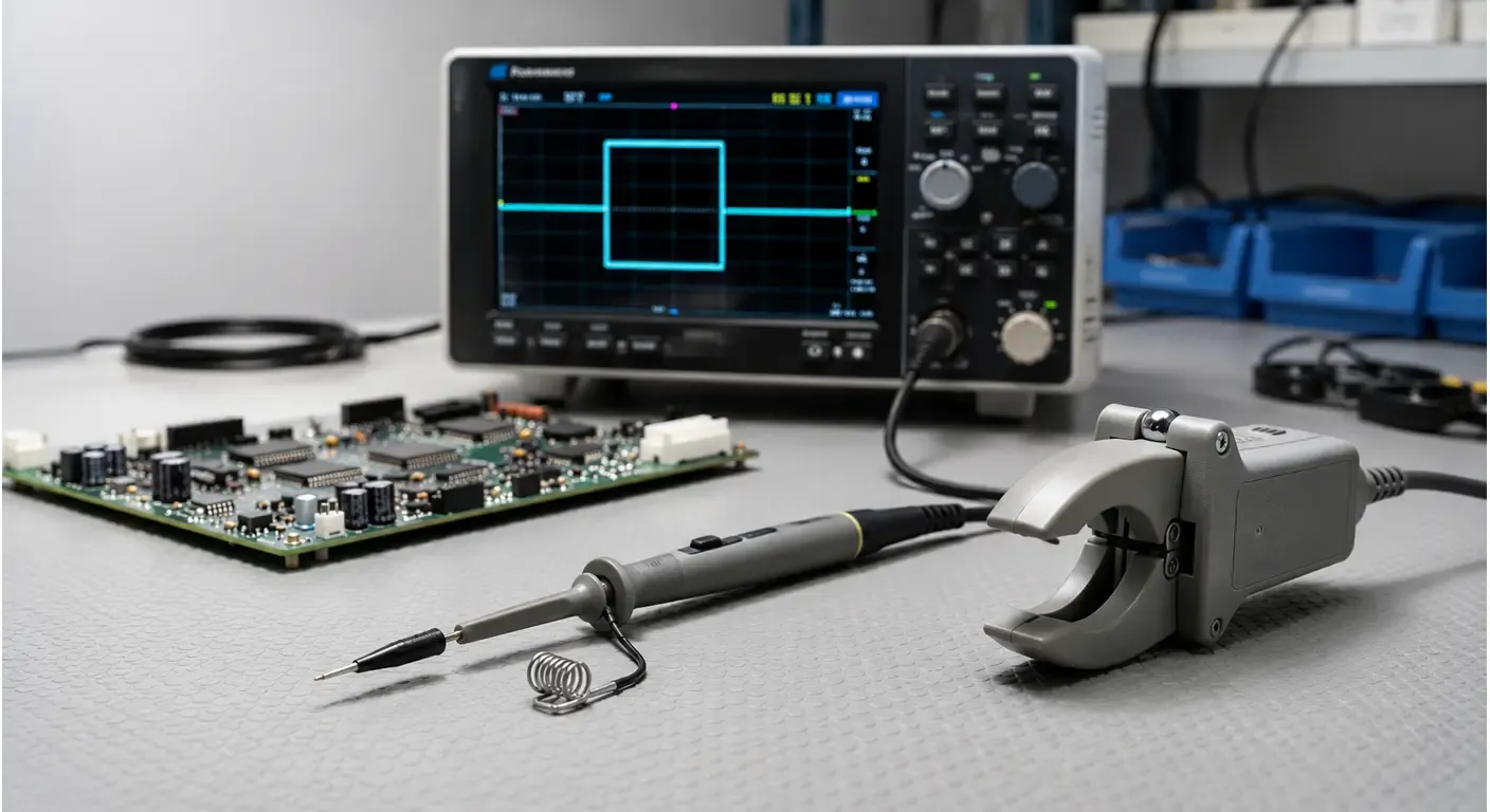
Electronics35 min read
A complete oscilloscope probe guide covering probe types, attenuation, bandwidth, loading, compensation, grounding and safety ratings for accurate measurements.
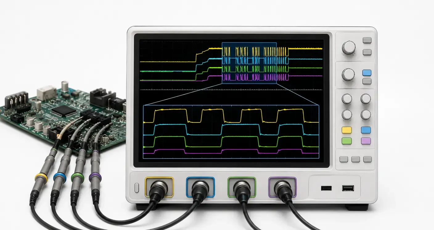
Electronics25 min read
Learn what oscilloscope memory depth is, how it affects sample rate and acquisition time, and how to choose the right memory depth for accurate signal analysis.
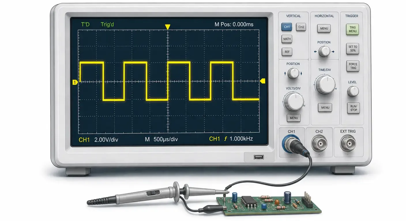
Electronics26 min read
Learn how oscilloscope triggering works, including edge, pulse, slope and video triggering, trigger level, holdoff and practical tips for capturing stable waveforms.
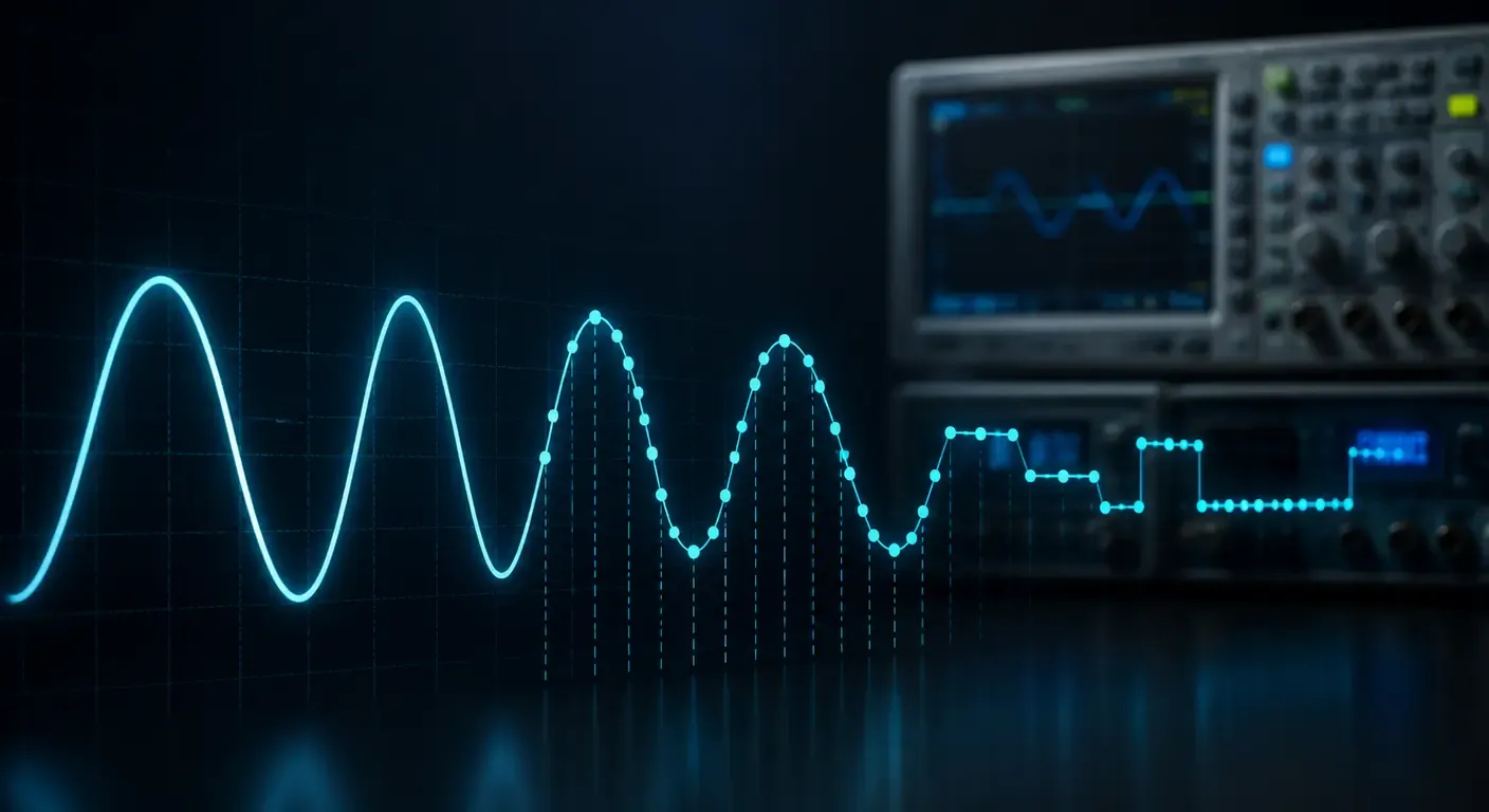
Electronics22 min read
Learn how oscilloscope sample rate affects waveform accuracy and aliasing, and how to read the figure correctly on a datasheet. Understand Sa/s and sampling fundamentals.
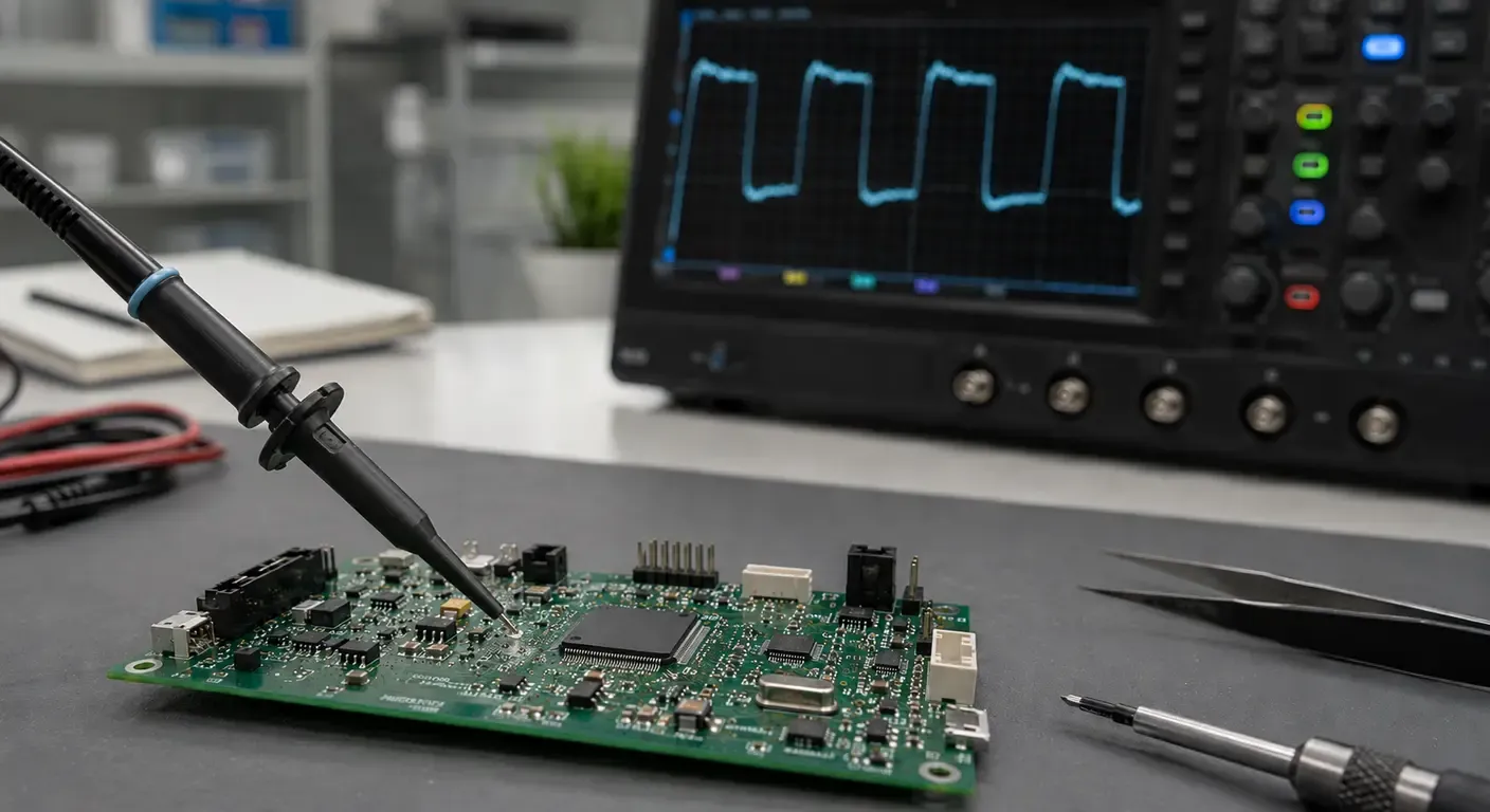
Electronics23 min read
Learn what an oscilloscope is, how it works, what it measures, and when to use one. Understand waveforms, bandwidth, sampling, probes and triggering in this engineering guide.
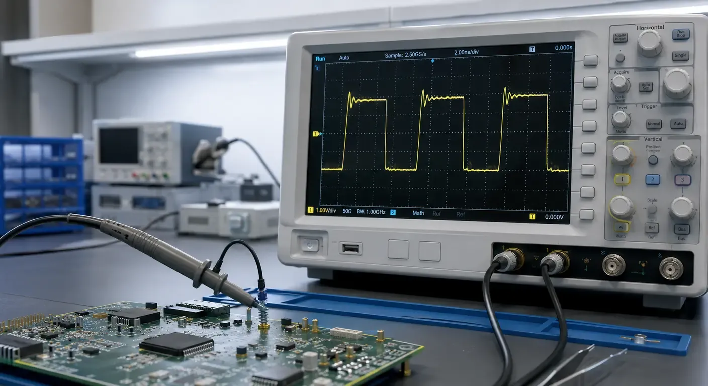
Electronics19 min read
Learn what oscilloscope bandwidth is, why it matters for accuracy, how it relates to sample rate and rise time, and how to choose the right bandwidth for your application.
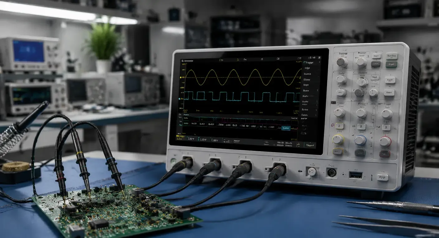
Electronics43 min read
Explore the best digital oscilloscopes for engineers and professional labs. Compare bandwidth, sample rate, memory depth, and key features to choose the right instrument.