Debugging High-Speed Serial Links
Techniques for eye-pattern analysis and jitter decomposition in PCIe Gen 5 designs — a field guide for when the link trains but will not stay up.
By YDT Editorial2 min read
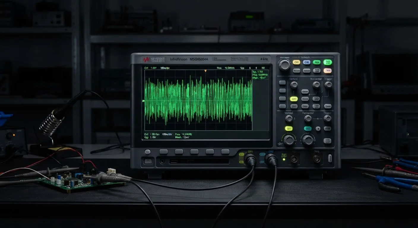
A PCIe Gen 5 lane runs at 32 GT/s, which means each unit interval lasts just over 31 picoseconds. At those timescales, a via stub is a resonator, a connector is a filter, and “it trains at Gen 4 speeds but drops to Gen 3 under load” is a symptom with a dozen possible causes. This guide covers the diagnostic sequence that separates them.
Start with the training log, not the scope
Before touching hardware, extract the link training and status state machine (LTSSM) history. Most root complexes expose it through vendor tools, and it answers the first triage question: is the link failing during equalization, or failing after achieving L0? Equalization failures point to channel loss and reflections; post-L0 instability under traffic points to crosstalk, power integrity, or thermal drift.
Recovery counts matter more than link state. A link sitting at Gen 5 with thousands of recovery entries per minute is a failing link that has not admitted it yet — expect throughput collapse under sustained load.
Eye diagrams: capture at the right reference plane
An eye captured at the transmitter tells you almost nothing about receiver margin. For meaningful measurements, use the receiver’s internal eye monitor if silicon exposes it, or de-embed the channel from a mid-bus probe measurement. The classic mistakes are measuring after the scope’s own equalization has flattered the signal, and comparing raw eyes against post-equalization compliance masks.
Jitter decomposition
Total jitter alone does not localize a problem; its decomposition does. Dominant periodic jitter at a switching regulator’s frequency implicates power delivery — check it against the rail spectrum. Rising deterministic jitter with a data-dependent pattern signals inter-symbol interference from channel loss. Unbounded random jitter growth usually traces back to the reference clock; measure its phase noise directly.
The checklist
Verify reference clock phase noise against spec. Confirm receiver termination and AC coupling values. Inspect back-drilled via stubs on the top-loss channels. Sweep temperature — marginal channels fail hot first. And when everything measures clean but errors persist, look at the retimer firmware version: more Gen 5 field failures resolve there than anyone’s schedule assumed.
Filed under
Related articles
Tutorials2 min read
Implementing PID Control on the ESP32
A practical walkthrough of discrete PID implementation on the ESP32 — timer interrupts, anti-windup, and tuning a thermal control loop.
Electronics21 min read
FFT on Oscilloscopes: Principles, Setup, and Interpretation
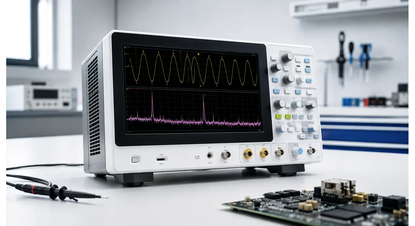
How an oscilloscope's FFT function works, how sample rate, record length and window functions affect the result, and how to interpret an FFT spectrum in engineering work.
Electronics22 min read
Sample Rate Explained: How Oscilloscopes Capture Digital Waveforms
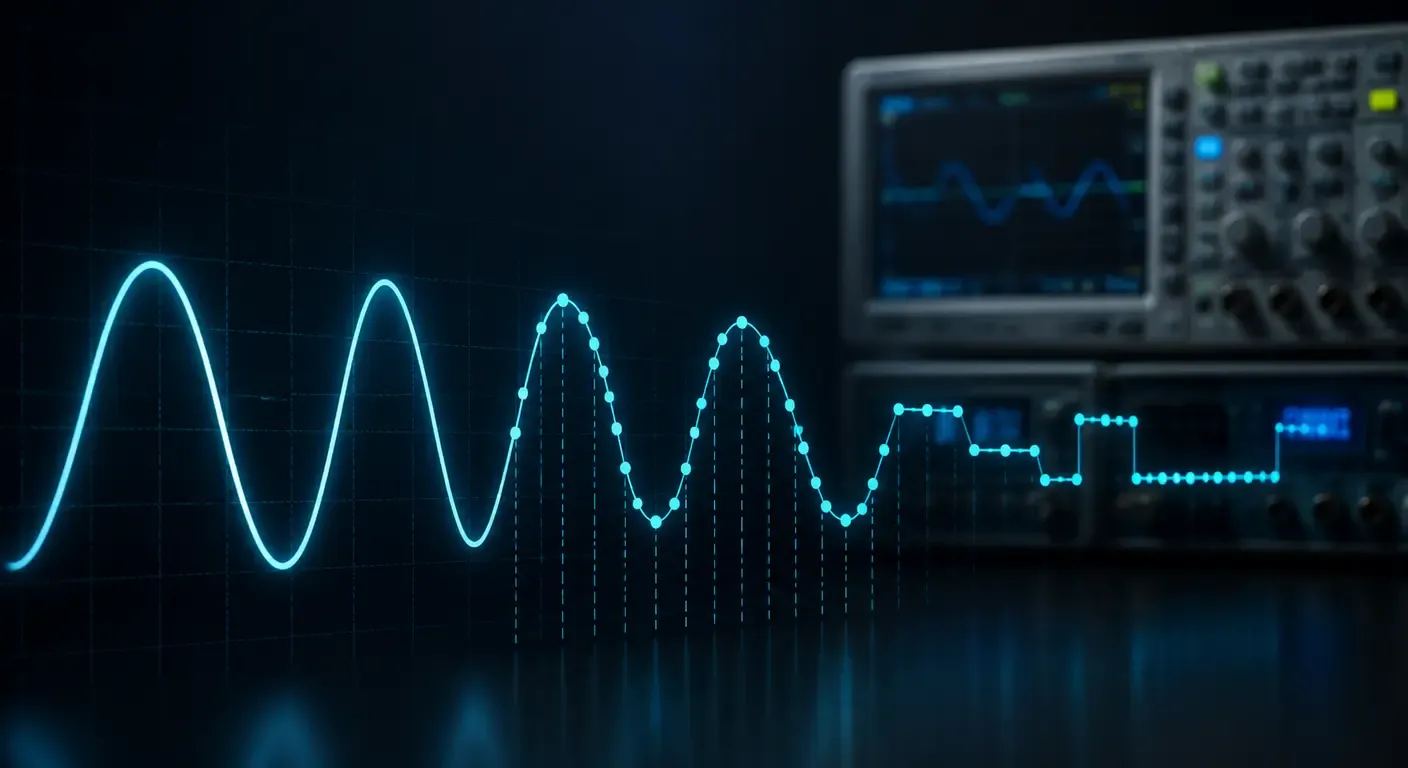
Learn how oscilloscope sample rate affects waveform accuracy and aliasing, and how to read the figure correctly on a datasheet. Understand Sa/s and sampling fundamentals.
Electronics19 min read
Understanding Oscilloscope Bandwidth: Definition, Measurement & Selection
Learn what oscilloscope bandwidth is, why it matters for accuracy, how it relates to sample rate and rise time, and how to choose the right bandwidth for your application.