Implementing PID Control on the ESP32
A practical walkthrough of discrete PID implementation on the ESP32 — timer interrupts, anti-windup, and tuning a thermal control loop.
By YDT Editorial2 min read
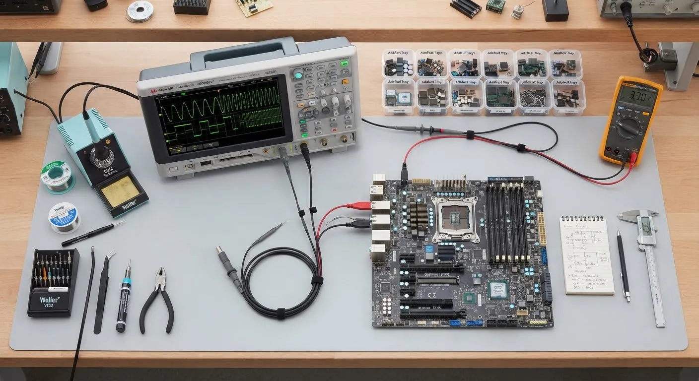
PID control is deceptively simple to write and genuinely hard to deploy well. This tutorial builds a discrete PID loop on the ESP32 for a thermal plant — a heater block with a thermistor — and works through the implementation details that separate a textbook loop from one that survives contact with real hardware.
The discrete form
The continuous PID equation needs discretization for a sampled system. The standard positional form works, but the velocity form has a practical advantage on embedded targets: it naturally avoids integral windup accumulation and makes bumpless setpoint changes easier.
float pid_update(pid_t *pid, float setpoint, float measured) {
    float error = setpoint - measured;

    pid->integral += pid->ki * error * pid->dt;
    pid->integral = clampf(pid->integral, pid->out_min, pid->out_max);

    float derivative = -(measured - pid->prev_measured) / pid->dt;
    pid->prev_measured = measured;

    float out = pid->kp * error + pid->integral + pid->kd * derivative;
    return clampf(out, pid->out_min, pid->out_max);
}
Two details matter here. The integral term is clamped to the output range — the simplest effective anti-windup. And the derivative acts on the measurement, not the error, so setpoint steps do not produce derivative kick.
Timing discipline
A PID loop’s dt must be constant, and loop() is not a scheduler. Use a hardware timer callback or a high-priority FreeRTOS task woken by vTaskDelayUntil at a fixed period — 10 Hz is ample for a thermal plant. Read the ADC with oversampling (16 samples averaged knocks down the ESP32 ADC’s noise substantially) and convert through a proper Steinhart–Hart fit rather than a linear approximation.
Tuning the loop
Skip Ziegler–Nichols for thermal systems; the induced oscillation is slow torture. Instead, characterize the step response: apply a fixed PWM step, log the temperature curve, and fit dead time and time constant. Lambda tuning from those two numbers gets within striking distance immediately, and the final adjustment is one rule: if it overshoots, cut Kp; if it oscillates slowly, cut Ki.
Log setpoint, measurement, and each PID term over serial while tuning. Watching the integral term saturate in real time teaches more about windup than any equation.
Filed under
Related articles
Tutorials2 min read
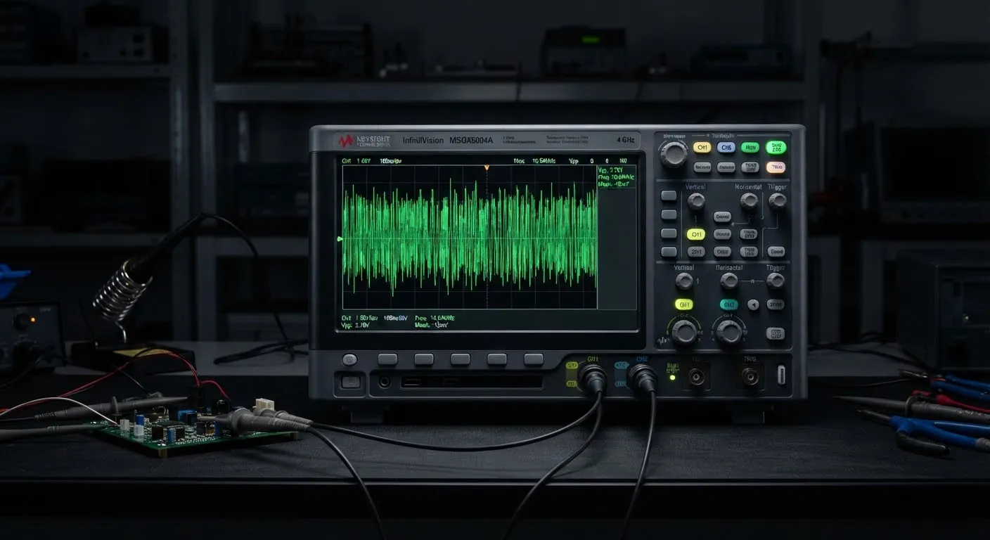
Debugging High-Speed Serial Links
Techniques for eye-pattern analysis and jitter decomposition in PCIe Gen 5 designs — a field guide for when the link trains but will not stay up.
Electronics18 min read
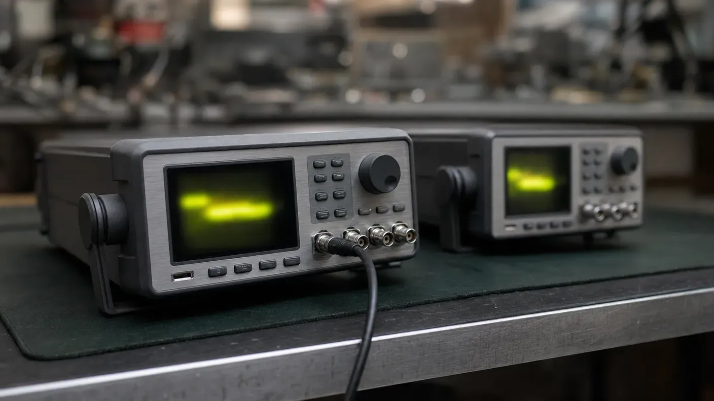
Function Generator vs Arbitrary Waveform Generator: What You Are Buying
Three names, two architectures: how DDS and point-by-point playback differ, what the labels hide, and how to read the architecture off a datasheet.
Electronics23 min read
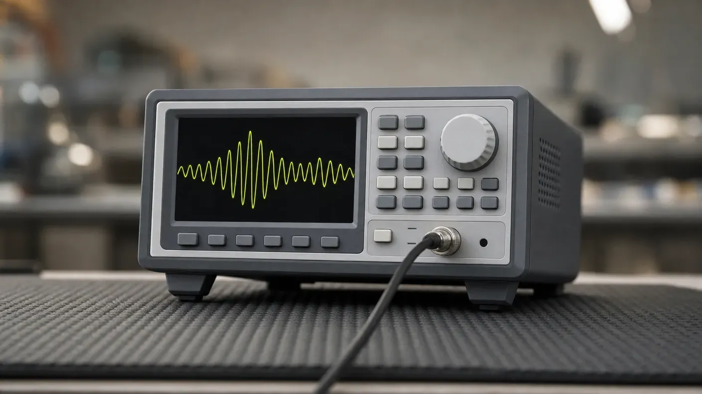
How to Choose a Signal Generator: Getting the Signal You Asked For
How to turn a required stimulus into datasheet requirements: the load the instrument assumes, bandwidth against sample rate, reconstruction and vertical resolution.
Electronics22 min read
How to Choose a Multimeter: A Specification-Led Buying Guide
Choose a multimeter by the errors it introduces: burden voltage, input loading, AC bandwidth, safety category and accuracy on the reading you actually take.