How to Choose a Multimeter: A Specification-Led Buying Guide
Choose a multimeter by the errors it introduces: burden voltage, input loading, AC bandwidth, safety category and accuracy on the reading you actually take.
By YDT Editorial22 min read
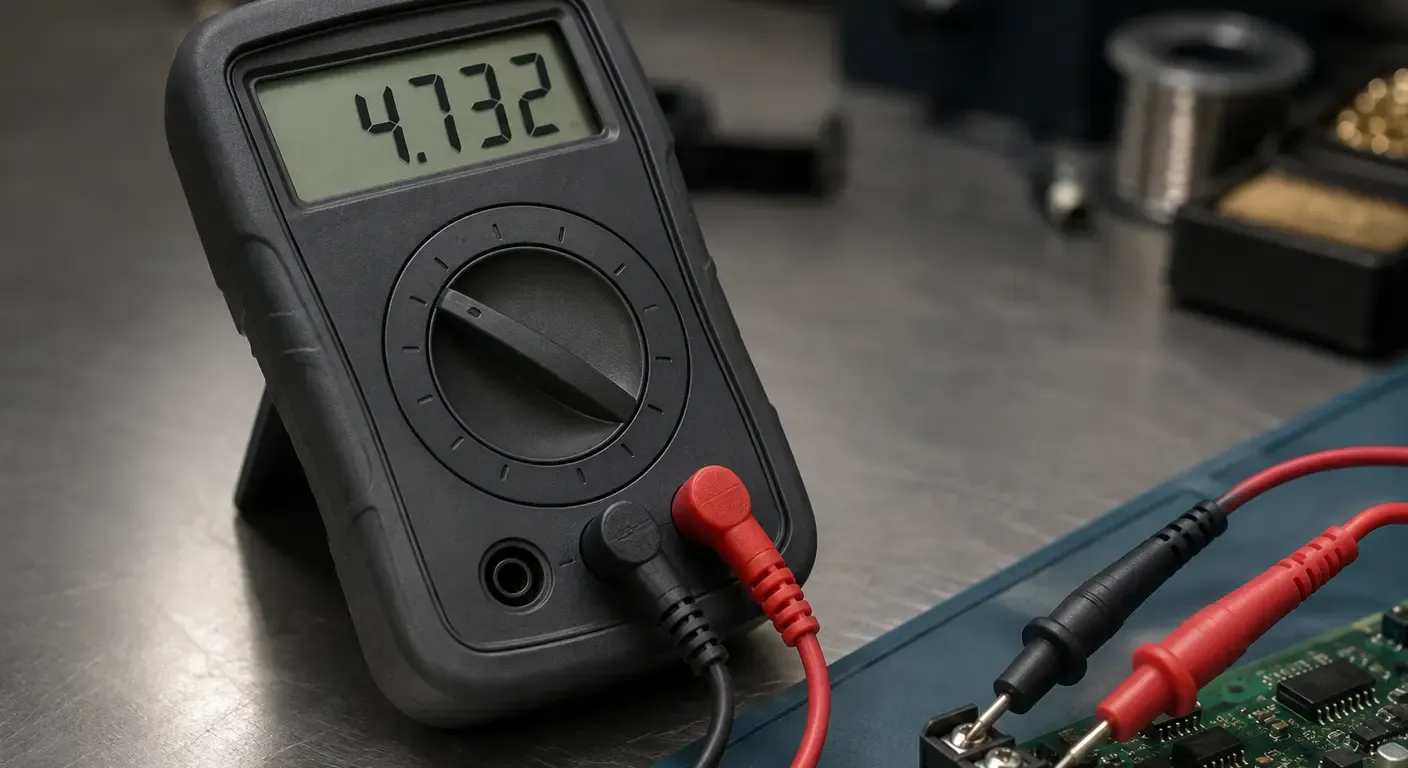
Choosing a multimeter is usually presented as a feature comparison: count of the display, list of functions, a safety marking on the case, perhaps a true RMS badge. That framing survives until the instrument reaches a real circuit, because it treats the meter as an observer of the measurement rather than as a participant in it.
Every reading a multimeter produces is the circuit plus the instrument. The meter draws current from the node it reads, develops a voltage in any path it joins, responds to only part of what the waveform actually contains, and reports the result through a display of finite resolution with a bounded error. Each line on a datasheet names one of those effects and puts a number on it. Read that way, a specification list stops being a ranking and becomes a description of how one particular instrument will degrade one particular measurement.
This guide works through safety category, accuracy notation, counts, burden voltage, AC bandwidth and input impedance as mechanisms rather than as features. It ends with a requirement profile — a short list of properties you can verify on any manufacturer’s published document before an instrument becomes a candidate. It names no products, because a framework that names products dates and the framework does not. For where the multimeter sits among the other instruments on a bench, start from the test and measurement instrumentation overview.
What a Multimeter Does to the Measurement
The moment the leads are connected, the instrument becomes a component in the circuit under test. It has an impedance, it occupies a path, it has a bandwidth and it has a settling time. The number on the display describes the circuit as modified by the instrument, not the circuit you intended to measure. Most of the time the difference is small enough to ignore. The engineering problem is knowing when it is not.
Four mechanisms account for almost every case where a reading misleads.
The instrument loads the node it reads, drawing current through its input impedance and pulling the node down by an amount that depends on the source impedance behind it. It develops a voltage in series when it measures current, and that voltage is subtracted from whatever the load would otherwise have received. It responds to a bounded portion of the waveform, so a signal containing energy outside that band is reported as smaller than it is. And it quantizes and bounds the result, through a display of finite resolution and an accuracy specification that varies across the range.
A fifth property is not a measurement error at all but a survival condition: the instrument has to withstand the transient energy available at the point where the leads are placed.
Choosing an instrument means deciding which of those mechanisms dominates in your work, and then requiring that the datasheet bound it. It is not a question of which meter is better. A multimeter answers what a quantity is, an oscilloscope answers how it changes, and choosing between instruments that observe behavior over time is a separate question again — see choosing between an oscilloscope and a logic analyzer.
Start From the Measurement, Not the Feature List
Four properties of the thing being measured bound the choice before any specification is read: the energy available at the point of measurement, the shape of the signal, the source impedance behind the node, and the magnitude of the current relative to the supply that feeds it. Every requirement that follows in this article derives from one of them.
In practice those four properties cluster into a small number of working profiles. Most engineers occupy one or two of them and buy for the rest by accident.
Mains and field work. Measurements at distribution boards, panels, motor branch circuits and building services. The dominant property is energy at the point: the instrument has to survive a transient that the circuit can deliver without limit. Signal shape matters where drives and electronic ballasts are present. Source impedance is low and irrelevant. This profile buys safety category first and everything else second.
Low-voltage electronics. Board-level work, regulator outputs, logic rails, battery packs. The energy at the point is bounded by the supply itself, so the category requirement collapses and resolution takes over. The difference the engineer needs to resolve is often tens of millivolts on a rail of a few volts, which is a question about counts and about which range the instrument is allowed to sit on.
Current in a running circuit. Measuring supply current without stopping the device: sleep current, quiescent draw, a load that only appears under operation. The dominant property is the ratio between the voltage the instrument develops in series and the headroom the supply has left. This is the profile that most often finds an otherwise good instrument unusable.
High-impedance nodes. Sensor outputs, dividers, unloaded conductors, long runs beside energized cable. The dominant property is source impedance, from both directions: the instrument may load a real node too heavily, or it may fail to load a coupled voltage that is not a real source at all.
These four names recur through the sections that follow, and the final section turns them back into a checklist. Identify which one describes most of your work before reading further, because the same specification is decisive in one profile and irrelevant in the next.
Safety Category: What CAT Rates and What the Marking Is Worth
A measurement category does not rate the voltage an instrument can read. It rates the transient energy available at the point where the leads are placed. The nearer the measurement point is to the origin of the installation, the less circuit impedance stands between it and the source, and the more energy a surge can deliver into the instrument before anything limits it.
This is why the category matters more than the voltage number printed beside it. A higher working voltage in a lower category does not substitute for a lower working voltage in a higher category: the two figures are not interchangeable, and it is the category that states how much energy the instrument was tested against. Read the category first, and the voltage beside it second.
| Category | Where the measurement is made | What bounds the transient |
|---|---|---|
| CAT I | Circuits not connected to the mains: secondary side of an isolating supply, battery-powered equipment | The source itself, which cannot deliver more |
| CAT II | Cord-connected loads at a socket outlet: appliances, portable tools, bench equipment | Impedance of the branch circuit and the cord feeding the load |
| CAT III | Fixed installation: distribution boards, breakers, fixed motors, hardwired branch circuits | Less circuit impedance to the supply; energy is high and only partly limited |
| CAT IV | Origin of the installation: service entrance, meters, the supply drop | Nothing between the point and the utility, including lightning-induced surges |
The second question is what the marking is worth. A hand-held multimeter is governed by three parts of the IEC 61010 series: IEC 61010-1 for the general safety requirements, IEC 61010-2-030 for equipment whose testing or measuring circuits connect to something outside the instrument, and IEC 61010-2-033 for hand-held multimeters, read in conjunction with 2-030. None of them is enforced by the IEC: nothing obliges a manufacturer to submit an instrument for third-party assessment, and nothing prevents it from evaluating its own product against those requirements and printing the result on the case.
What distinguishes an assessed instrument from a declared one is the presence of a listing mark from a recognized testing body — UL, CSA, TÜV, VDE and their equivalents — usually accompanied by a file or certificate number that can be looked up in that body’s own register. That mark is the only element on the instrument attesting that a third party ran the tests. Treat it as a specification and verify it the way you would verify a bandwidth.
Reading an Accuracy Specification
Accuracy on a digital multimeter is almost always written as a percentage of the reading plus a fixed number of counts. Those two terms behave in opposite directions across a range, which is why the headline figure on the front of a datasheet answers nothing on its own. The only useful form of the specification is the one evaluated at the reading you are actually going to take.
Take an instrument specified ±(0.5 % of reading + 3 counts) on a 6,000-count display. That is a hypothesis stated here for the arithmetic, not a manufacturer’s specification. On the 6.000 V range, the display shows three decimal places, so one count is 1 mV.
- Reading 3.750 V. The proportional term is 0.5 % of 3.750 V, or 18.75 mV. The fixed term is 3 counts, or 3 mV. Total uncertainty ±21.75 mV, which is 0.58 % of the reading.
- Reading 0.500 V on the same range. The proportional term falls to 2.5 mV, but the fixed term is still 3 mV. Total ±5.5 mV, which is 1.1 % of the reading — nearly double, for a signal the instrument is nominally well within specification to measure.
- Reading 0.500 V on the 600.0 mV range. One count now represents 0.1 mV. The proportional term is unchanged at 2.5 mV, the fixed term collapses to 0.3 mV, and the total is ±2.8 mV, or 0.56 %.
Same instrument, same signal, half the error, because the counts term scales with the range rather than with the reading. One caution on the arithmetic: it holds the same accuracy specification across both ranges, which published documents often do not — a millivolt range frequently carries its own percentage and its own counts term, and a real comparison uses the figures given for each range. What survives that caveat is the mechanism. Range selection is a measurement decision, not a convenience, and an instrument that autoranges aggressively upward at the moment of connection can cost more accuracy than the difference between two datasheets.
Why Counts Is a Resolution Figure, Not an Accuracy Figure
Counts describes how finely the display can divide a range. A 6,000-count instrument shows a maximum of 5999 before it changes range; a 20,000-count instrument shows 19999. Bench instruments are usually specified in digits instead. The two forms describe the same property but do not convert cleanly. The half-digit form is unambiguous: 20,000 counts is what a bench specification calls 4½ digits, a leading digit restricted to 0 or 1. The three-quarter form is not — it is used both for a leading digit reaching 3, which is 4,000 counts, and for one reaching 5, which is 6,000. Where a specification gives digits alone, read the maximum displayed value off the range table rather than converting.
The property both forms describe is the size of the smallest increment the instrument can display. It says nothing about whether the displayed value is correct. A high-count instrument with a loose accuracy specification resolves an error it cannot bound, and it will do so with reassuring stability.
Counts becomes the binding constraint in exactly one situation: when one count on the range you are forced to use is coarser than the difference you need to resolve. Measuring a few tens of millivolts of drop across a connection, while the range is set by the full rail voltage, is the ordinary case. Establish that increment before comparing accuracy figures, because an instrument that cannot show the difference will not be rescued by being right about the value.
Measuring Current Without Changing It
A multimeter measures current by placing itself in series with the load and reading the voltage that develops across a shunt inside it. That voltage does not come from nowhere. It is taken from the supply, and it no longer reaches the load. The instrument reports the current flowing in a circuit it has just made slightly worse.
The total is larger than the shunt alone. The current path runs through the shunt, a fuse, the range-switching contacts, the input jacks and the test leads, and every element in that chain contributes. The published figure — burden voltage — covers the instrument’s internal path and is the parameter that decides whether a current measurement is viable at all.
Burden voltage is normally expressed as millivolts per milliampere, or as a full-scale burden voltage for a given range. Both forms describe the same thing: the slope of instrument voltage against measured current. It is specified per range, and the ranges do not behave uniformly. A lower current range generally uses a larger shunt to preserve resolution, so it can develop more voltage per milliampere than a higher one, not less. A single figure quoted without a range is not a specification.
Two consequences follow for selection. First, an instrument that does not publish burden voltage anywhere in its documentation should be treated as unspecified on this parameter rather than assumed adequate; the absence of the figure is itself information. Second, comparing two instruments on this parameter requires comparing them on the same range, at the same current, in the form the manufacturer published — never a figure carried over from another instrument or estimated from a shunt value.
When Burden Voltage Disqualifies the Instrument
While the voltage the instrument develops is small against the supply rail, the effect is a correctable error: the load runs slightly below its normal supply voltage, the current is slightly lower than it would otherwise be, and for most purposes the reading is usable.
The measurement stops being correctable when the developed voltage is a significant fraction of the headroom the circuit has. A low-voltage rail, a linear regulator already near dropout, or a device whose behavior changes as its supply sags — a radio that will not transmit, a processor that resets, a sleep mode that never entrains — all fail in the same way: the instrument perturbs the circuit into a different operating state and then reports the current drawn by that state. No amount of accuracy in the shunt measurement recovers the number you wanted.
At that point the answer is a different measurement principle, not a better ammeter. A clamp meter senses the field around a conductor without series insertion, so it carries no burden at all, at the cost of a resolution floor and the need for a single accessible conductor. A dedicated current instrument holds the burden low by regulating it actively, and is the usual answer where the currents span several decades.
Where True RMS Stops Being Enough
A true RMS claim on a datasheet is not yet a specification. It becomes one when the frequency range over which it holds is stated beside it, because the AC signal path in every multimeter has a bandwidth, and outside that bandwidth the converter continues to produce a number without any indication that the number has become wrong.
This is the failure mode that makes the parameter worth checking. An out-of-band component is not flagged, it is simply attenuated on its way to the RMS converter, so the instrument reports a value lower than the true one and reports it steadily. A stable reading is not evidence of a correct one.
The AC path of a general-purpose instrument is specified over a band bounded at both ends, and its upper bound is usually far below what a chopped or switched waveform contains. That matters because the waveforms engineers most want an RMS value for — the output of a drive, the input current of a switch-mode supply, a phase-controlled load — carry significant energy well above the fundamental. Whether an instrument covers them is not deducible from the presence of the true RMS label; it is stated, or it is not.
Three things to look for in the AC specification, and what their absence means:
- The frequency band the AC accuracy is specified over, usually as a separate accuracy figure for each of two or three sub-bands. If no band is given, the claim is unbounded and therefore unverifiable. Treat it as unspecified.
- Whether the measurement is AC-coupled. Most AC ranges exclude the DC component, so a waveform with an offset — as a chopped or rectified signal usually has — is reported as the RMS of its AC part only. An instrument that reports the RMS of the complete signal states an AC+DC capability explicitly.
- The crest factor limit, where one is given. It is a separate bound on how peaky a waveform the converter can handle within specification, and it is stated independently of the frequency range.
An instrument that publishes all three is making a claim you can check. An instrument that publishes the words “true RMS” and nothing else is asking to be trusted on a parameter it has declined to define.
Input Impedance and the Circuit You Disturb
A voltmeter completes a path across the node it measures, and current flows in that path. The instrument’s input impedance and the source impedance behind the node form a divider, so the measured voltage is always lower than the undisturbed one. Whether that matters is a ratio, not a threshold.
Take the common 10 MΩ DC input and a node fed through a source impedance of 1 MΩ. The divider gives 10/(10 + 1) of the true value, so the instrument reads about 9 % low — an error larger than anything in its accuracy specification, produced by an instrument working perfectly. Against a source impedance of a few kilohms the same input is invisible. The question to ask of a high-impedance profile is not what the input impedance is, but what it is compared with the node.
The same choice appears inverted in field work. A conductor running for some distance beside energized cable, and disconnected at both ends, will show a voltage on a 10 MΩ input: the capacitance between the conductors couples charge onto it, and an instrument that draws almost no current does not discharge it. The reading is real, the source is not, and treating it as a live circuit costs time.
A deliberately low-impedance mode — commonly labeled LoZ — is the answer. It places a low resistance across the node on purpose, drawing enough current to collapse a capacitively coupled voltage while leaving a genuine source essentially unaffected. That is the entire diagnostic: a voltage that survives loading is fed by something; one that disappears was coupled.
These are usually presented as two unrelated features, one for electronics and one for electricians. They are the same decision, taken in opposite directions — how much do you want the instrument to load the node. The corollary is a caution: because a low-impedance mode draws real current, it does not belong in the high-impedance profile, where it will collapse the signal you were trying to measure and may load a source that cannot supply it.
What a Datasheet Does Not Tell You
Several properties decide whether an instrument is pleasant or intolerable to use, and none of them is ranked anywhere.
Reading rate. How many times per second the display updates, and whether a changing value can be followed at all. A slow display averaged over a long conversion cannot show a value moving under a slowly varying load, and a bar graph is usually the only fast indication on the instrument. Sometimes stated in the manual as readings per second; often not.
Autorange settling. The delay between connection and a stable reading, and the behavior when a value sits near a range boundary and the instrument oscillates between ranges. Manual ranging is faster and, as the accuracy arithmetic showed, often more accurate. Whether manual ranging is one button or a menu is established by handling the instrument, not by reading about it.
Continuity beeper latency. The interval between contact and sound decides whether a brief intermittent is detected or missed entirely. This is almost never specified. It is established by trying the instrument, or by a review that measured it.
Fuse type and replaceability. The current inputs are protected by high rupturing capacity fuses, and the relevant questions are whether the fuses are a standard part, whether they are available separately, and whether reaching them requires disassembly past a sealed barrier. The replacement part numbers are in the manual, which is published before purchase.
Leads and probes. Leads carry their own category and voltage rating, and the assembled instrument is governed by the lowest rating in the chain. Supplied leads are frequently rated below the meter they ship with. The rating is printed on the lead itself and is worth reading before assuming the instrument’s marking applies to the whole assembly.
Turning This Into a Requirement Profile
The output of this article is a short list you can carry to any manufacturer’s documentation. Work through it once, in this order, using the profile from the second section that best describes your work.
- Energy at the point of measurement. Name the highest-energy location you will place leads on, and require the corresponding category and working voltage — then require the listing mark and file number of a recognized testing body. Both, or neither counts.
- Smallest difference you must resolve. State it in the units you work in, identify the range that will be selected when you measure, and check that one count on that range is finer than the difference. This is a counts requirement and it is separate from accuracy.
- Accuracy at your actual reading. Take the published percent-of-reading-plus-counts figure and evaluate it at the low end of the range you will use, as in the worked example above. Compare instruments on that number, never on the headline.
- Signal shape. If any measured waveform is not a clean sinusoid, require true RMS with a stated frequency band covering your content, and decide whether you need AC+DC rather than AC-coupled.
- Current in a live circuit. Require a published burden voltage for the specific range you will use, and compare it against the supply headroom of the circuit you will insert into. If the instrument does not publish one, it is unspecified on the parameter that decides the measurement.
- Source impedance, both directions. Compare the input impedance against the highest source impedance you will meet, and decide separately whether you need a deliberately low-impedance mode for coupled voltages.
- Practical constraints. Reading rate, manual ranging, fuse type and availability, and the category rating of the leads.
Anything on that list that cannot be checked against a published document before purchase is a risk you are accepting knowingly rather than a specification you have verified. That distinction, applied consistently, does more for the quality of a measurement than any single line on a datasheet.
Frequently Asked Questions
Does a higher count display make a multimeter more accurate?
No. Counts bounds the smallest increment the display can show, while accuracy bounds how far the displayed value may be from the true one. A high-count instrument with a loose accuracy specification resolves an error it does not bound.
What is a CAT rating worth on an instrument with no listing mark?
It is the manufacturer's own declaration that the product meets the requirements, made without independent verification. The listing mark and file number of a recognized testing body is the only marking on the instrument that attests to a third-party test.
Why does my current reading differ from what the circuit actually draws?
Because the instrument develops a voltage across its own path when placed in series, and that voltage is subtracted from the supply reaching the load. On a circuit with little headroom the load changes state, and the meter correctly reports the current of the disturbed circuit.
Is true RMS always necessary?
Only where measured AC waveforms depart from a sinusoid, which in practice means anywhere drives, switch-mode supplies or phase control are present. Where it is required, the claim is only actionable with the frequency band it is specified over.
Why does my meter read a voltage on a wire that is disconnected at both ends?
A high input impedance draws too little current to discharge a voltage coupled capacitively from nearby energized conductors. A deliberately low-impedance mode loads the node enough to collapse a coupled voltage while leaving a genuine source intact.
Related articles
Electronics18 min read
Function Generator vs Arbitrary Waveform Generator: What You Are Buying
Three names, two architectures: how DDS and point-by-point playback differ, what the labels hide, and how to read the architecture off a datasheet.
Electronics23 min read
How to Choose a Signal Generator: Getting the Signal You Asked For
How to turn a required stimulus into datasheet requirements: the load the instrument assumes, bandwidth against sample rate, reconstruction and vertical resolution.
Electronics16 min read
How to Use a Thermal Camera: Getting Readings You Can Trust
A thermal camera always shows a number. Learn the checks — emissivity, reflected temperature, focus and spot size — that decide whether it is a measurement.
Electronics21 min read
FFT on Oscilloscopes: Principles, Setup, and Interpretation
How an oscilloscope's FFT function works, how sample rate, record length and window functions affect the result, and how to interpret an FFT spectrum in engineering work.