How to Use a Thermal Camera: Getting Readings You Can Trust
A thermal camera always shows a number. Learn the checks — emissivity, reflected temperature, focus and spot size — that decide whether it is a measurement.
By YDT Editorial16 min read
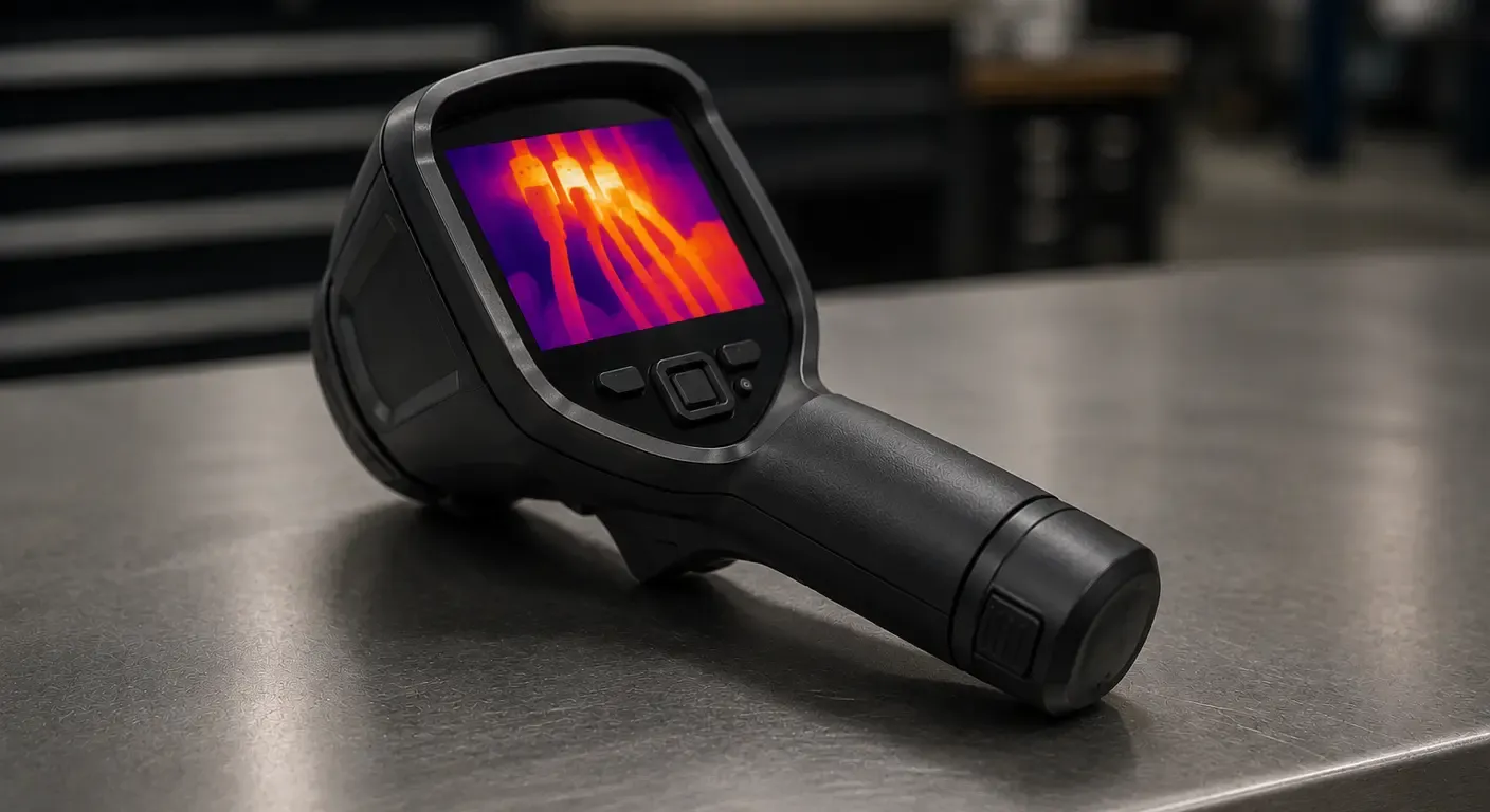
Point a thermal camera at a terminal lug and it returns a number. Nothing on the display distinguishes the temperature of the lug from the temperature of the ceiling reflected in it, or from the average of the lug and the air around it. All three render as the same confident figure.
That figure becomes a measurement only under conditions, and every one of those conditions can be checked before the shutter. This guide sets out the checks: what the camera is physically responding to, whether the job needs an absolute value at all, the settings that decide whether the displayed value corresponds to the surface in front of the lens, why some targets cannot be measured however clearly they appear on screen, and how to separate a reflection from an emission while still standing in front of the equipment.
What a Thermal Camera Actually Measures
A thermal camera is a passive instrument. It emits nothing and probes nothing: it collects infrared radiation arriving from the direction it is pointed and builds an image from it. Because the radiation leaving a surface is a function of that surface’s temperature, the camera can work backwards from radiance to a temperature and display one.
The radiation reaching the detector, however, is not a function of the object’s temperature alone. It depends on the object’s emissivity — how efficiently that particular surface radiates — it includes radiation from the surroundings reflected toward the lens, and it has been modified on the way by absorption in the intervening atmosphere. The three contributions arrive superimposed, and the detector cannot separate them.
The camera separates them arithmetically, and only from what it is told. FLIR’s camera documentation lists five object parameters used for that compensation: the emissivity of the object, the reflected apparent temperature, the distance between object and camera, the relative humidity, and the temperature of the atmosphere. Everything the instrument knows about the physical situation, it knows from those five values.
Left at their factory settings, what the display shows is an apparent temperature — an uncompensated reading, a measure of the radiance reaching the detector rather than of the object’s temperature. It is not the surface temperature carrying a known error bar. It bears no reliable relation to it.
One limit is structural rather than a matter of settings. A thermal image is built almost entirely from radiation emitted or reflected by the surface facing the camera.
Qualitative or Quantitative: The Decision That Shapes Everything Else
Before any parameter is entered, decide what the job has to produce. Thermography splits into two modes, and they impose different obligations.
Qualitative work locates thermal patterns. It answers questions of the form which of these is hotter than the others, and it needs no absolute value: one connection against its two neighbors, one phase against the other two, one motor against the same motor last quarter. Most electrical and electronics inspection is comparative in exactly this way. Settings still matter, but what they have to be is consistent across the comparison rather than correct in absolute terms.
Quantitative work reports an absolute surface temperature. That requires emissivity and reflected apparent temperature to be established for the actual surface being measured rather than assumed, and it requires the geometric conditions covered further down to hold.
The second mode costs more than it appears to. FLIR is explicit that compensating correctly for emissivity may require thermography training, and recommends certification before attempting measurements on difficult surfaces — a manufacturer telling users that a setting on its own instrument is not self-explanatory.
| Qualitative survey | Quantitative measurement | |
|---|---|---|
| What the camera must be told | Enough to keep every frame comparable with the others | Emissivity and reflected apparent temperature established for this surface |
| What the image must contain | The suspect component and at least one comparable component in the same conditions | The target overfilling the measurement spot, in focus, at a known distance |
| What it licenses you to conclude | This connection runs hotter than its neighbors; this phase differs from the other two | This surface is at a stated temperature, with a stated uncertainty |
| What it will not support | Any absolute figure, and any comparison against a published threshold | Anything the settings were not established for |
Deciding the mode first prevents the most common waste on site: hours spent chasing an emissivity value for a survey whose conclusion was always going to be comparative.
The Four Settings That Decide Whether the Number Is Real
Of the five parameters above, the operator sets three on site: emissivity, reflected apparent temperature, and the distance-and-atmosphere group. The fourth item in this section is not a parameter at all. Focus appears nowhere in the compensation arithmetic, and nothing in that arithmetic compensates for getting it wrong.
Emissivity
Emissivity measures how efficiently a surface radiates — how well it tells the truth about its own temperature, in FLIR’s phrasing, or, in the camera documentation’s shorter form, how much radiation the object emits compared with a perfect blackbody at the same temperature. It runs from 0 to 1 in theory, and FLIR’s own published figures for the practical span of real materials differ between two of its pages, so the useful thing to carry is not a boundary but a set of anchors. Highly polished copper or aluminum sits below 0.10. The same metal roughened or oxidized rises to 0.6 or above depending on surface condition. Most flat-finish paints are around 0.90, and skin and water are about 0.98.
It is the parameter FLIR names as the most important to set correctly, and the sensitivity is not subtle. FLIR shows one substation disconnect whose maximum apparent temperature ranged from 118 °F to 194 °F — roughly 48 °C to 90 °C — across three different emissivity settings applied to the same target.
Why a low value is dangerous deserves stating separately. As emissivity falls, a shrinking fraction of what the camera sees originates in the target and a growing fraction originates in whatever the target reflects. Past a certain point the instrument is largely reporting the room.
Reflected apparent temperature
Reflected apparent temperature is the thermal radiation from surrounding objects that reflects off the target toward the lens. It is a separate setting from emissivity, and it is not the ambient air temperature. The two are routinely conflated, and the consequences of conflating them are not symmetrical.
It is measured rather than assumed. Crumple a large piece of aluminum foil, uncrumple it, place it facing the camera in front of the target, set emissivity to 1.0, and read the foil’s apparent temperature. The foil behaves as a near-perfect reflector, so what it appears to be is the reflected apparent temperature of the surroundings.
The setting matters most where emissivity is low and the object’s temperature is far from that of its surroundings. Where emissivity is high, reflected temperature has little influence, and FLIR’s own worked example for skin — at an emissivity of 0.98 — simply uses the environmental temperature. Treating ambient as a proxy is defensible on a high-emissivity target. The rule to measure rather than assume binds where emissivity is low, which is where it was always going to matter.
Distance and the atmosphere
The distance entry compensates for two effects at once: radiation from the target absorbed by the air between object and camera, and radiation emitted by that same air and detected along with it. Atmospheric transmittance also depends on relative humidity, which FLIR states can normally be left at its default of 50 % for short distances and normal humidity.
Short is doing real work in that sentence. FLIR’s accuracy analysis is valid for laboratory use or short range, which it defines as less than 20 m outdoors. Beyond that, atmospheric absorption and, to a lesser degree, atmospheric emission introduce uncertainty that entering a distance does not remove.
Focus
Focus is not a question of picture quality. An out-of-focus thermal image reads low: the peak values it reports fall below the true ones, and having every other parameter correct does not rescue them. Fluke publishes dedicated guidance on focusing for that reason.
FLIR states the position without hedging. Focus must be perfect each time before an image is saved, and when it comes to focus there is no such thing as good enough — it is either in focus or it is not. On a camera with manual focus, that is a deliberate step taken at the target, every time.
Why the Camera Shows a Number It Cannot Measure
A thermal camera has two spatial specifications, and only one of them is usually quoted.
The instantaneous field of view, IFOV, is the angular size of a single detector pixel. Each pixel defines a potential measurement spot, so IFOV describes what the camera can display — the finest detail that can appear in the image at all.
Accurate temperature measurement needs more than one pixel. The measurement field of view, MFOV, is the area the instrument requires for a valid reading, and it usually spans about 3×3 pixels. MFOV describes what the camera can measure. The gap between the two is where most bad readings come from, because IFOV appears on every datasheet and MFOV frequently does not.
Instrument makers define the boundary in energy terms rather than geometric ones. Optris specifies the minimum spot size as the spot diameter at which the instrument detects 90 % of the target’s energy, and expresses the geometry as a distance-to-spot ratio: measurement distance divided by spot size. Whatever the notation, the requirement is the same — for an accurate reading the target must be at least the size of the measurement spot.
The working rule on site is blunt. Put at least 3×3 pixels on the target, and make the target overfill the camera’s spot measurement tool rather than merely sit inside it.
When the target is smaller than the measurement spot, the reading is an average of the target and whatever surrounds it. A small hot component against cooler board or cooler air is therefore under-reported, and the direction of that error is the dangerous one: the survey understates the very thing it was run to find. The recorded value is that average.
Digital zoom does not help. It enlarges pixels already captured, adds no optical resolution, and changes nothing about how much of the target falls inside the measurement spot. The image gets bigger and the measurement does not get better.
The remedies are all physical. Get closer, where it is safe to do so. Fit a narrower field of view, or an optical telephoto lens. Use a detector with more pixels. There is no setting for this.
What the Display Shows, and What It Hides
Level and Span set the brightness and contrast of the thermal image, and FLIR’s measurement procedure has them adjusted before temperatures are read. They change nothing radiometric, but they change what the image appears to say: the same data spread across a narrow span produces alarming structure, and across a wide span produces a flat gray field. A screenshot is not evidence of severity unless the span is known.
The palette is the operator’s own choice. One functional reason to change it exists.
Reflections are the other thing the display hides, and the field test for them costs nothing: move. Change viewing position and watch the feature. A hot or cold spot that travels with the camera is a reflection from another source; one that stays put is emitted by the surface in front of you.
A reflection is not corrected by adjusting emissivity. It is handled physically — by changing angle, by treating the surface, or by measuring somewhere else. Since the incident angle equals the reflection angle, the viewing position determines which sources enter the line of sight at all, and a localized source can often simply be blocked. The failure mode is not exotic: FLIR shows an electrical bus bar connection reading falsely hot purely from a reflection.
Where Thermal Imaging Stops
Some targets defeat the instrument regardless of how carefully it is configured. Recognizing them early saves the effort of correcting something that cannot be corrected.
Bare, reflective metal. Correction stops working when emissivity is low, and the manufacturers do not quite agree on where that is: Fluke places the boundary at 0.6, FLIR at 0.5. The disagreement matters less than the conclusion they share — the temperature of most bare metals cannot be measured accurately, and the limitation applies to every thermal imaging system rather than to a particular model. It is compounded when the reflected temperature is very different from the surface temperature.
The workaround is to give the camera a surface it can read. A small piece of electrical tape, pressed firmly onto the metal and left to reach its temperature, presents an emissivity of about 0.95; with an appropriate reflected-background correction, Fluke states that ±2 °C or 2 % of measurement can be achieved this way. FLIR’s camera documentation uses the same tape method when determining an unknown emissivity. Where tape cannot be applied, an oxidized or painted part of the same assembly is often the better place to measure.
Glass. Window glass is quite reflective in the thermal infrared, which is why Fluke applies the same tape technique to cold glazing that it applies to shiny steel. A pane read directly is largely reporting whatever faces it.
Targets below the measurement spot. Covered above, and repeated here because it belongs on the same list: no configuration recovers a target smaller than the spot, and the remedy is optics or working distance.
Where the surface defeats radiometry, the answer is a different instrument rather than a better setting — a contact sensor, or another part of the electronic test and measurement toolkit, applied where the camera cannot help.
A Repeatable Inspection Procedure
The order below is not arbitrary. Each step either constrains the next or becomes impossible to redo once the equipment has been left behind.
-
Confirm access and safety, and let that set the working distance. Distance is bounded by what can be approached safely, not by what the lens can resolve. FLIR lists long-distance measurement among the options precisely for situations where getting closer is dangerous or impractical, and cautions against approaching equipment unless it is safe to do so. If safe access forces a distance at which the target falls below the measurement spot, the survey is qualitative — decide that now rather than afterwards.
-
Put the equipment in a representative operating state. A thermal survey answers a question about equipment as it runs. An assembly inspected unloaded, or a drive inspected before it has reached steady state, produces images that are not so much wrong as irrelevant. This is a practical condition of the inspection, not a camera setting.
-
Let the camera warm up, and keep it out of the sun. The instrument’s own temperature affects its readings. FLIR instructs allowing a full warm-up before critical measurements, and keeping the camera and its optics away from direct sunlight and other heat sources.
-
Choose the viewing position with reflections in mind. Look for possible reflection sources before framing, knowing that the incident angle equals the reflection angle. A localized source can be obstructed with something as simple as a piece of cardboard.
-
Determine reflected apparent temperature first, then emissivity. That is FLIR’s order, and it holds because the emissivity determination is itself read against the reflected value.
-
At the moment of reading, focus, auto-adjust, freeze the image, then set Level and Span. Take the value from the frozen, focused, correctly scaled image rather than from the live view.
-
Record what was set, not only what was read. FLIR’s emissivity procedure explicitly instructs writing down the values found — the apparent temperature measured on the foil, and the final emissivity. A reference image captured at each inspection point is what turns a one-off survey into comparable historical data for the next one.
A record carrying the image but not the parameters cannot be compared with anything, including a later image of the same asset taken by the same person with the same camera.
Frequently Asked Questions
Do I need to set emissivity if I am only comparing components?
Comparative work does not need a correct absolute value, but it does need a consistent one. Use the same emissivity setting across every frame in the comparison, and do not compare an image taken at one setting with an image taken at another.
Is reflected apparent temperature the same as room temperature?
No. It is a separate setting describing radiation from the surroundings reflected off the target, and it is measured with an aluminum foil reflector. Ambient temperature is a defensible substitute only on high-emissivity targets, where reflected radiation has little influence.
Why does the reading change when I move?
Because part of what the camera sees is reflected rather than emitted. A feature that travels with the camera as the viewing position changes is a reflection from another source; a feature that stays fixed on the surface is emitted by it.
Can I zoom in on a small component instead of getting closer?
Not usefully. Digital zoom enlarges pixels already captured and changes nothing about how much of the target falls inside the measurement spot. Only a shorter working distance, a narrower field of view, an optical telephoto lens or a higher-resolution detector improves the measurement.
Why can a shiny copper bus bar not be measured accurately?
Its emissivity is far too low, so most of what the camera collects comes from surrounding objects rather than from the bus bar. Apply a high-emissivity patch such as electrical tape, or measure at an oxidized or painted point on the same assembly.
Related articles
Electronics18 min read
Function Generator vs Arbitrary Waveform Generator: What You Are Buying
Three names, two architectures: how DDS and point-by-point playback differ, what the labels hide, and how to read the architecture off a datasheet.
Electronics23 min read
How to Choose a Signal Generator: Getting the Signal You Asked For
How to turn a required stimulus into datasheet requirements: the load the instrument assumes, bandwidth against sample rate, reconstruction and vertical resolution.
Electronics22 min read
How to Choose a Multimeter: A Specification-Led Buying Guide
Choose a multimeter by the errors it introduces: burden voltage, input loading, AC bandwidth, safety category and accuracy on the reading you actually take.
Electronics21 min read
FFT on Oscilloscopes: Principles, Setup, and Interpretation
How an oscilloscope's FFT function works, how sample rate, record length and window functions affect the result, and how to interpret an FFT spectrum in engineering work.