ESD Workstation Setup: Grounding, Layout and Assembly
How the elements of an ESD workstation bond to a common point ground, where each one belongs on the bench, and what layout mistakes survive a component check.
By YDT Editorial25 min read
A workstation can pass every item check on its list and still fail as a system. The mat measures within range. The wrist strap tests good at the start of the shift. The floor was qualified when it was installed.
Then look at the bench itself. The mat takes its ground from the frame, the shelf that went up last summer was never bonded to anything, and a plastic parts bin sits within arm’s reach of the spot where boards come out of their bags — because that is where the operator can reach it. Every element on the checklist is still compliant. Nothing on the checklist looks at how those elements were joined, or at what has since been put between them.
What holds a device at a safe potential is the way the pieces are connected, where they sit relative to the point at which devices are actually exposed, and what else shares that space. This guide covers that part: how the elements of a workstation bond to a common point ground, how the bench is laid out around the handling point, the order in which a station is brought into service, and the layout errors that survive an item-by-item check. It does not cover how to choose any individual element.
Why a Workstation Is a System, Not a Bill of Materials
What a workstation has to achieve is narrower than the list of things standing on it. For as long as a device is exposed, the operator, the worksurface and the device itself have to sit at one shared potential, and anything entering that space has to be brought to the same potential before it is close enough to matter.
Everything on the bench serves that end: the surface mat, the flooring beneath it, wrist straps and their ground cords, seating, footwear and heel grounders, storage containers and process packaging, smocks and gloves, and the instruments used to check any of them. Each has its own requirements and its own way of degrading. None of them creates a shared potential by itself.
Take a bench built entirely from qualified parts — a certified dissipative mat, compliant seating, a floor that was tested at installation — and hang an unbonded stainless shelf over it two years later because the totes had nowhere to go. Every item on the audit list still measures in range. The shelf is not on the list, and it is the only thing on that bench that changed.
That is the blind spot of an item check. It answers whether a component still behaves the way it did when it was qualified. It says nothing about whether the components are joined to each other, whether the arrangement survives one connection degrading, or whether something ungrounded has moved into reach of an exposed device. Those are properties of the assembly. What a site has to specify and document about them belongs to the control program standard, ANSI/ESD S20.20, and is treated in how an ESD control program defines grounding and bonding requirements.
The normative text of these standards is licensed and is not reproduced here. What is attributed to them below rests on material the publishing body issues itself and on publisher-supplied preview pages.
The Common Point Ground
Every grounded element on the bench meets at one place, and one conductor leaves that place for the building. How those two statements are implemented is most of the electrical design of a workstation.
One Point, Independent Connections
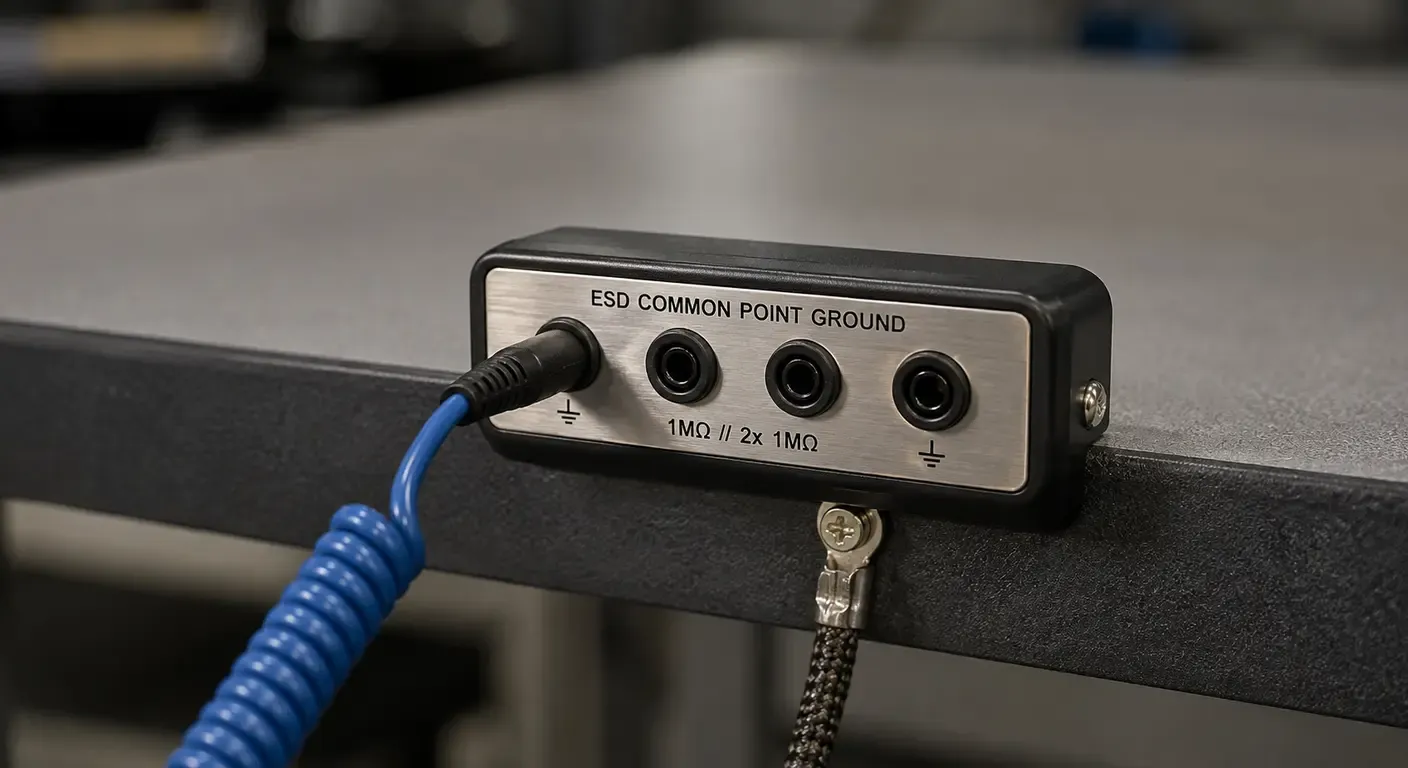
A common point ground is the single conductive point the grounded elements of the workstation are connected to: the worksurface, the wrist strap receptacle, a bonded fixture, a metal shelf, bonded seating. The requirement is that none of them takes its ground through another element of the workstation.
Benches are often assembled the other way, because it is easier to build. The mat bonds to the frame, the frame carries the strap receptacle, the receptacle’s ground continues to the next element, and one conductor finally leaves for the wall. Measured element by element, the two arrangements are indistinguishable. Everything reads continuous, everything is connected to ground, and the check confirms it.
The difference appears when a connection degrades. Where each element has its own conductor, a failing link drops one element out of the shared potential and leaves the rest alone. Where elements sit behind one another, that link is a common failure point: everything depending on it loses its reference at once, and those are the elements least likely to be suspected, because their own connections are intact and still test correctly.
Whether the conductors physically radiate from a single stud or simply land independently on a grounding bar is a hardware question. What matters is the dependency between elements, not the geometry of the wiring.
Where the Ground Point Sits on the Bench
Placement is a layout decision rather than an electrical one, and it is usually settled by whoever drills the holes. Two conditions drive it. The connection has to be reachable without passing a hand or a cord over the area where devices are exposed. And the operator’s cord has to reach it without lying across the worksurface, because a cord that gets dragged and snagged is a cord that gets unplugged — and after a few days nobody plugs it back in.
Fitting the point at the front edge, below the worksurface and on the side the operator works from, usually satisfies both. That is ergonomics rather than an electrostatic requirement: a bench worked from the opposite side, or shared by two operators, puts it somewhere else.
The Path Out of the Bench
From the common point, one conductor leaves the bench and lands on the equipment grounding conductor of the building’s power distribution — the same ground the instruments on the bench already use. That is the whole path: elements to the common point, common point to equipment ground. ANSI/ESD S6.1, the standard covering grounding for the protected area, describes it in those two stages and treats the equipment grounding conductor as the preferred connection.
Where an auxiliary ground exists, S6.1 has it bonded into the same system rather than used in its place. The idea that an ESD workstation needs its own dedicated earth, isolated from the building’s, is one of the most persistent errors in this subject. An isolated ground gives the bench a reference that can differ from the reference of every instrument plugged into it, which is precisely the condition equipotential bonding exists to prevent.
How that final connection is actually made — where it lands, with what hardware, and who is permitted to make it — falls under the electrical code applicable to the installation, and that document is not the same from one country to the next. The ESD requirement fixes the destination; the wiring rules that get you there are local ones.
The Worksurface: Where Cleanroom and ESD Requirements Disagree
Two sets of requirements arrive at the same piece of furniture, usually written by different people. Contamination control asks for a face that is non-porous, chemically resistant to whatever the room is wiped down with, and that neither sheds fibers nor traps residue in a damaged surface — which is why stainless steel is such a common answer in a cleanroom. Electrostatic control asks something else of the same face: that a charged device set down on it loses its charge through a path with enough resistance in it to keep the transfer slow. The worksurface is where that tension is most visible, but it runs through every element of static control in a cleanroom environment: cleanliness and charge control are separate requirements, answered by the same hardware.
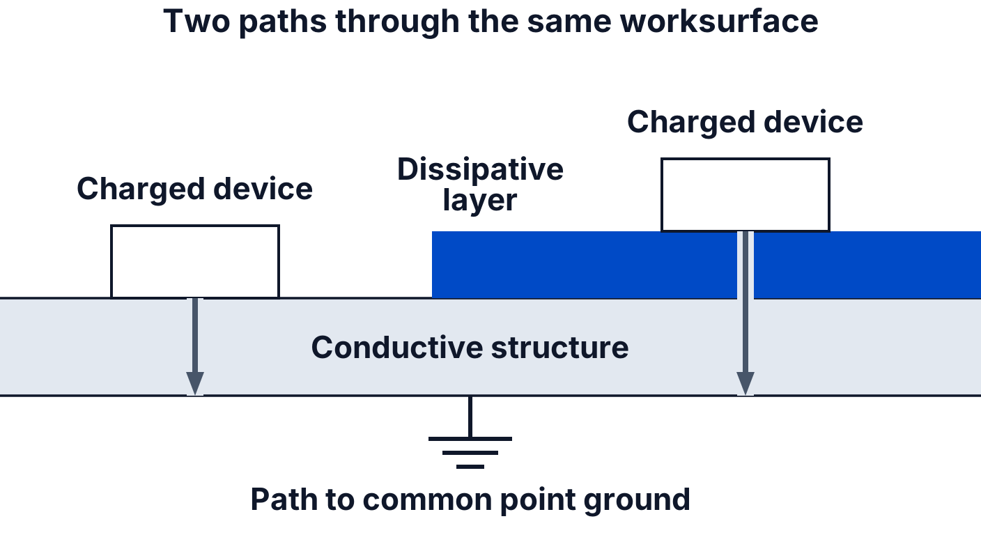
Bare metal answers the first requirement and not the second. On a grounded metal top the contact is metal to metal, and the transfer is far faster and far less controlled than on a surface designed to slow it. Whether a particular device survives that depends on the device and on how much charge it was carrying — but the surface does not provide the same controlled discharge behaviour as a dissipative ESD worksurface, which is the point. It is the case where intuition built on wiring, where a good ground and a low resistance mean better protection, points the wrong way.
| Requirement regime | What it pushes the surface toward |
|---|---|
| Particle and contamination control | Non-porous, seamless, chemically resistant, cleanable without shedding |
| Electrostatic control | Enough resistance in the path to slow the transfer, little enough to still remove the charge |
Neither requirement is negotiable, so both have to be satisfied on the same bench. The usual way of doing that is to separate them within the stack rather than to arbitrate between materials. Cleanability is a property of the top face; resistance is a property of what sits between the device and the conductive structure underneath it. A dissipative layer over a grounded conductive support is the common arrangement, and it works because the device meets a controlled path while the room sees a continuous face it can clean.
It is not the only workable arrangement, and the layer is not selected on its electrical properties alone. Cleaning chemistry and frequency, solvents and fluxes used in the process, temperature, and the particle class of the room all constrain what can go on top of a bench. A material that is electrically ideal and degrades under the room’s cleaning agents is not a candidate for that room. What does generalize is where the protection sits: in the thickness the device rests on, not in the quality of the horizontal path to ground. Improving the ground connection of a bare metal top improves nothing that matters.
How much resistance the surface has to present, and how that value is bounded, is a program requirement rather than a bench decision. It sits in the EPA control items table and the limits it states, alongside the other items an area has to keep within range.
Laying Out the Bench Around the Handling Point
The handling point is the small volume in which a device is out of its packaging and exposed. Layout is organized around that volume, not around the bench.
Watch how a layout actually forms. An operator pulls a board out of its shielding bag, sets the empty bag down on the left because both hands are needed, and puts the plastic tote it arrived in on the right, where there is space. The board goes back into a bag at the end of the sequence. Nothing in that is careless. By the following week the tote lives there: the shelf it came from is two steps away, the sequence works, and nobody ever decided anything. An object that entered the handling zone once because it was convenient has become a permanent part of the bench — and it will still be there at the next audit, which will find every listed element in range.
What Must Not Sit Within Reach
Everything on a bench falls either inside the volume an operator sweeps while a device is exposed, or outside it. The boundary is not marked on anything. It is the reach of a seated operator turning between the handling point and whatever they pick up most often.
Inside belongs what the work requires: the surface, the device, the tooling that touches it, and the containers it arrives and leaves in. The rest goes further away — process paperwork in polymer sleeves, adhesive tape rolls, unbonded plastic bins, wrapping film, personal items. Each of them holds a charge that nothing on the bench will remove, and each can act on an exposed device without ever touching it.
Moving an object out of the zone costs nothing, and it keeps costing nothing. A control installed to compensate for leaving it there has to be specified, funded, verified periodically, and re-verified whenever someone moves or replaces it — and between two verifications it can be quietly ineffective. That is the argument for the shelf on the other side of the room: not that it is more rigorous, but that there is nothing about it to maintain and nothing about it to get wrong.
Insulators That Cannot Be Removed
Some insulators cannot leave. Consider a test fixture whose body is machined from a polymer because it has to be non-marking, dimensionally stable and cheap to replace, and into which a board is dropped several hundred times a shift. The alternative material does not exist in the process as it is qualified. The same goes for a device’s own housing, or for packaging that has to be opened at the bench.
The decision here is not “plastic is bad, remove the plastic”. It is what to do about a charged surface that has a reason to be there. Distance is the first variable and the only one layout controls: the fixture gets as much separation from the exposed device as the sequence allows, and its position is fixed rather than left to whoever sets up the shift. Where the process will not permit that separation, what remains is to control the field the object carries or to neutralize it, which is where ionization enters — and only there. How charge acts on a device at a distance is treated alongside the control program requirements and is not replayed here.
Fixtures, Jigs and Isolated Conductors
A third category sits between the two: metal that is present, ungrounded, and not practically bondable. An insert molded into a fixture, a screw in a plastic housing, a connector shell on a subassembly with no path to anything. Each floats at whatever potential its surroundings left it with, and hands that potential to the first thing it touches.
Where such a conductor can be bonded, it is bonded and the question closes. Where it cannot be grounded or equipotentially bonded, and where it can interact with an exposed device, the process step containing it has to be qualified instead: S20.20 states the condition an isolated conductor has to meet inside an EPA as a voltage on that conductor of less than 35 V.
That figure belongs to that situation and does not travel with the metal. It is not a limit to hold every isolated piece of metal in the area against, and it is not a routine bench measurement. It is established once, against the actual fixtures in the actual sequence, and what satisfying it requires depends on the step being qualified. An operator cannot confirm it by looking, and no continuity check implies it.
Shelving, Lighting and Airflow
A bench in a general assembly area can carry a solid shelf above the worksurface and lose nothing. Under unidirectional downflow, the same shelf becomes something that has to be evaluated rather than simply installed.
Downflow air arrives vertically and leaves through the floor or low returns, carrying particles away from the work. A solid horizontal surface set in that path splits the flow, and depending on its size, its height above the worksurface, its position relative to the returns and how the room itself was designed, it can leave a recirculating region beneath it — often over the handling point, since that is where a shelf is useful. Whether it does, and how much it matters, belongs to the room’s airflow layout rather than to a rule that can be settled at the bench. That uncertainty is why shelving, light fixtures, monitor arms and cable trays are commonly specified as perforated or open frames, and why the volume directly above the handling point is kept as clear as the work allows. Which rooms run that regime at all follows from how cleanrooms are classified by particle concentration.
The electrostatic requirement pulls the other way. Every structure added above the bench is either a conductor, in which case it is one more element that has to reach the common point ground on its own conductor, or an insulator, in which case it is one more charge source hanging directly over an exposed device — in exactly the position the reach zone exists to keep clear.
One way to satisfy both constraints is to use an open conductive structure and bond it to the common point ground. A perforated steel shelf on a bonded frame satisfies both. An open polymer rack satisfies the airflow requirement and creates an electrostatic problem in the hardest place to mitigate one, since it is neither removable nor reachable. Being open settles the particle question and nothing else.
Lighting gets missed more often than shelving, because a lamp is not thought of as bench equipment. It is metal, and it hangs above the handling point. A task light clamped to the back rail six months after the station was accepted, or a monitor arm bolted on when the bench got a second screen, arrives with no bond and no mention in anything describing the station. Electrically it is an isolated conductor in the worst available position. Procedurally it is a change to an accepted configuration that nobody recorded. Both are closed the same way: a conductor to the common point, and a line in the record saying the arm is there.
One further element sits in the personal path rather than above the bench. A cleanroom smock is worn over the operator’s own clothing and comes between the body and the bench, which is why that path is designed around the garment rather than through it.
When Local Ionization Belongs at the Bench
Ionization is a complementary control. It earns its place at a bench when the insulators that matter are ones the process needs and layout cannot deal with — objects that cannot be removed, cannot be replaced by a dissipative equivalent, and cannot be moved far enough away. Within that scope it does something nothing else does: it neutralizes charge on an object that has no path to ground.
Outside that scope it mostly conceals work that was not done. A plastic bin, a tape dispenser, a document sleeve — these can leave, and a unit bought to cover them is equipment paying for a shelf in another room. The objects also multiply once it runs, because the visible consequence of adding one more has disappeared.
Where ionization is justified, coverage is the parameter that decides whether it works. A unit covers a volume, and the volume that has to be covered is the one where devices are actually exposed. Take a two-meter bench with a bar-type unit mounted centrally, which is where the brackets fit and where the bench looks symmetrical. If the operator works at the left-hand end, what was specified as coverage for the bench is not coverage over the handling point, and a verification made under the middle of the bar says nothing about the corner where the boards come out of their bags. Airflow complicates it further, since downflow carries ionized air away from wherever it was aimed. Which unit, mounted where, and verified how belong to selecting an ionizer for a cleanroom environment.
Bringing the Station Into Service
The order of assembly is not administrative. Grounding is the part that becomes hard to reach later: once the shelves are up, the fixtures are placed and the equipment is on the bench, the frame, the underside of the worksurface and the wall connection are all behind something. A ground conductor added at that stage gets routed where there is room rather than where it belongs — draped over a cable tray, landed on whichever bolt is still accessible, or taken to a painted bracket that looks like bare metal. It also gets verified exactly once, at the point where a failed check would mean undoing the installation. That check tends to pass.
So a station is built outward from the ground, in the order that keeps each step verifiable before the next one hides it.
- Establish the path out of the bench first. The equipment ground connection and the conductor from the common point are in place and confirmed before anything is mounted on the bench.
- Fit the common point ground where the layout requires rather than where drilling is easiest, and confirm it is reachable without crossing the worksurface.
- Bond the worksurface, then each remaining element, each on its own conductor to the common point. Taken one at a time, the element being added is the only variable; taken together, none of them is.
- Add the structures above the bench — shelving, lighting, arms — and bond each one as it goes up. This is the step most often done later by someone else, and the step that most often goes unbonded.
- Place fixtures and tooling, then settle the handling point by watching the work rather than by reading the drawing. Run a real sequence with the operator who will do it, including the steps before and after, and note every object that enters the reach zone while it runs. Some of those objects need a bonded home inside the zone; the rest go out. A layout accepted on paper has been accepted against work nobody has done yet.
- Bring in the work. The bench is now a station, and anything added after this point is a change to an accepted configuration.
The station is then verified as a system, against the compliance verification plan of the program governing the area. What gets measured, with what, and how often is that plan’s business rather than the bench’s. What the bench owes is a configuration in which the requirements a control program has to document can be met and defended.
Layout Mistakes That Survive a Component Check
Each of the following passes an item-by-item check. Every element measures within range, every connection reads continuous, and the station still does not do what it was built to do.
Everything behind one connection. A bench is assembled with the mat bonded to the frame, and the shelf, the fixture plate and the strap receptacle all picking up their ground from that frame in turn, with a single conductor leaving for the wall. Element by element, it measures correctly — every one of those measurements ends at the same wall connection, and that connection is sound on the day it is made. Some months later the bench is shifted a few centimeters during a maintenance visit and the joint at the frame is disturbed. Four elements lose their reference at once. Three of them will not be measured again until the next scheduled check, and the one thing exercised daily, the operator’s strap test, reports the strap, the cord and the contact at the wrist. The integrity of the reference behind the receptacle is a separate question on a separate schedule.
The shelf that solved the wrong problem. A technician mounts a perforated stainless shelf over the bench so the totes stop sitting on the worksurface. It is open, it is bonded, and it passes on both counts. It also sits directly above the handling point, which is the one volume the layout was trying to keep clear, and the totes it holds are now above exposed devices rather than beside them. The useful question before it goes up is not whether the shelf complies, but what will be stored on it and where that puts the contents relative to the boards.
The remaining ones are quicker to describe and no easier to see:
- An auxiliary ground used in place of the equipment grounding conductor. The bench is grounded, measurably — to a reference the instruments standing on it do not share.
- A bare metal top used as the worksurface. Cleanable, durable, perfectly bonded, and offering a charged device a path with nothing in it to slow the transfer.
- An ionizer installed to cover insulators that could have been removed. The reading improves, the unit gets its periodic verification, and the bench goes on collecting objects that never belonged on it.
- A common point ground fitted where the cord has to cross the worksurface to reach it. The connection is sound, the operator is working unplugged by the end of the week, and nothing in the ground path would measure differently.
Frequently Asked Questions
Does an ESD workstation need its own dedicated ground rod?
No. The bench bonds to the equipment grounding conductor of the building's power distribution, the same ground the instruments on it already use. An isolated earth gives the bench a reference the equipment does not share. Where an auxiliary ground exists, it is bonded into the same system rather than used in its place.
Can an ESD bench be grounded to a water pipe?
Not as the workstation ground. The connection point is the equipment grounding conductor of the electrical installation. Plumbing is not one: its continuity depends on what the pipe is made of and on fittings that can be replaced with plastic ones during any maintenance, with nobody relating that work to the bench. How and by whom the connection is made is governed by the electrical code applicable to the installation.
Can a stainless steel top be used as an ESD worksurface?
Not bare. As the conductive support beneath a dissipative layer, the same top is a normal arrangement: the resistance that limits the discharge belongs in the layer the device rests on, not in the connection to ground. The layer also has to survive the room's cleaning agents and process chemistry, which is usually what narrows the choice.
Does every workstation need an ionizer?
No. Ionization addresses charge on insulators the process needs and layout cannot deal with. Where an object can be removed or moved away, that is the control. Where a unit is justified, its coverage has to include the point at which devices are exposed, not simply the bench it is mounted on.
What is the difference between grounding and equipotential bonding at a workstation?
Grounding gives the bench a path to a reference. Bonding is what makes the elements share it. Several elements each running their own conductor to a different ground point are all grounded and can still sit at different potentials; landing them on one common point is what makes the shared potential a property of the assembly rather than of each item.
What happens when a monitor arm or a shelf is added after the station was accepted?
It is a change to the configuration and is treated as one. A conductive structure mounted over the bench reaches the common point ground on its own conductor; an insulating one becomes a charge source in the position hardest to mitigate. Either way the addition belongs in the record of what the station was accepted with, or the next person comparing the bench against its description has nothing to compare it to.
Does a cleanroom workstation need different grounding from a general assembly bench?
The architecture is the same: elements to a common point, common point to equipment ground. What changes is everything around it. The surface has to satisfy cleaning and particle requirements at the same time as electrostatic ones, structures above the bench have to stay open to the airflow and bonded, and the smock sits in the personal path.
Filed under
Related articles
Electronics14 min read
ESD Ionizer Maintenance: Cleaning, Service, and What a Failed Check Means
A failed charged plate monitor reading is a maintenance trigger. How to localize the fault, clean and service an ESD ionizer, and know when cleaning is no longer the answer.

Electronics13 min read
How to Test an ESD Ionizer with a Charged Plate Monitor
Offset voltage has a fixed limit; discharge time does not. How to run a charged plate monitor check, read the result, and know which standard applies.

Electronics15 min read
ANSI/ESD S20.20: How an ESD Control Program Is Defined, Qualified and Verified
How ANSI/ESD S20.20 defines an ESD control program, what product qualification establishes, and how compliance verification keeps it demonstrable.

Electronics17 min read
ISO 14644: How Cleanroom Classification Works
What an ISO 14644 class number actually asserts, how a classification is demonstrated and kept valid, and where the series deliberately stops.