How to Choose an Ionizer for a Cleanroom
Choosing an ionizer for cleanrooms means balancing ESD performance against particle contamination — selection criteria for airflow, emitters and specs.
By YDT EditorialUpdated 18 min read
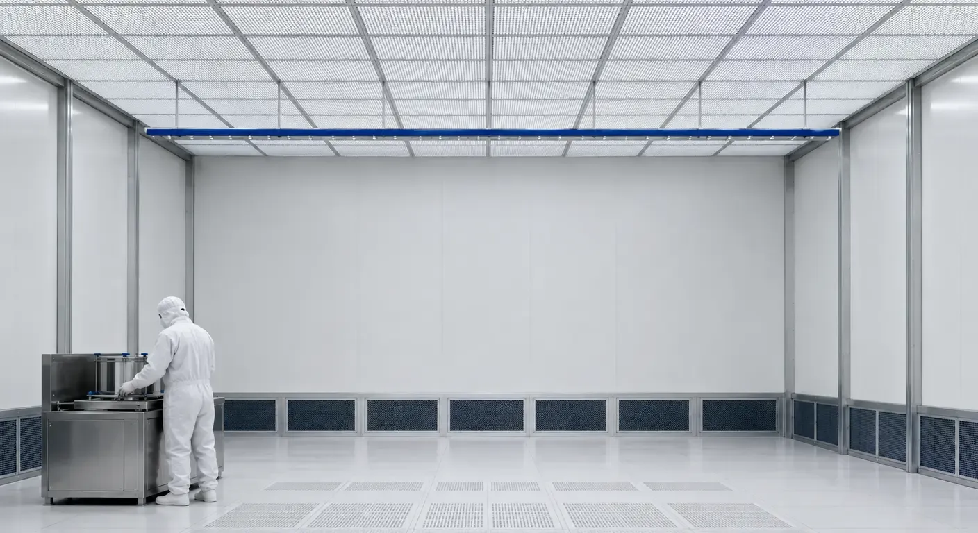
An ionizer that meets every ionization requirement in ANSI/ESD S20.20 on an assembly bench can still be the wrong device to install above a cleanroom process station. Nothing about its electrostatic performance changes when it crosses the airlock. What changes is that a second, unrelated acceptance criterion now applies to it at the same time.
Inside a controlled environment, an ionizer fills two roles that pull in opposite directions. It is a charge control device, judged in volts of offset and seconds of decay. It is also a physical object placed in a filtered airstream with a high-voltage discharge at its working end, judged in particles per cubic meter. The first role is governed by ANSI/ESD S20.20 and IEC 61340-5-1. The second is governed by the ISO 14644 series and by whatever contamination control plan the facility operates under. Neither family of standards defers to the other, and neither one will tell you that your ionizer selection has failed the other.
That is the gap this guide addresses. The questions that actually decide a cleanroom ionizer purchase — where ions are generated, how they are transported, what the emitter is made of, how often someone has to gown up to clean it — are largely absent from a general ESD equipment specification.
What follows assumes you already know how ESD ionizers work. It superimposes cleanroom constraints onto an otherwise ordinary ionizer selection, in the order they should be considered.
Start From the Charge Problem, Not the Product Category
Selection normally starts with a product category — a bar, a blower, a ceiling system. That order hides the question that actually constrains the choice: what is holding charge, and how close does it get to the product?
In a controlled environment the charge inventory is rarely the parts themselves. It is the process insulators around them: carrier and pod bodies, reticle enclosures, tape and release liner, packaging film, gloves and garment surfaces. It includes isolated conductors — a lead frame on a tray, an ungrounded fixture insert, a metallized layer on an otherwise insulating carrier — which are the objects ANSI/ESD S20.20 addresses with its 35 V limit, one of the requirements an ESD control program has to satisfy. And it includes moving webs and films, which regenerate charge continuously instead of holding a fixed value.
Two numbers fall out of that inventory, and neither comes from a datasheet. The required decay time follows from process tempo: how long a charged surface sits near the product before it must be neutralized, which is a property of the handling sequence. The required offset limit follows from the withstand voltage of the most sensitive item handled in that zone. A CDM-sensitive die on an exposed lead frame and a packaged assembly in a tray do not need the same balance.
Ionization is the last layer, not the first. It applies only to charge that could not be designed out or drained away, which is what the ESD control hierarchy establishes.
The third output of the inventory is location. If charge accumulates across an entire bay, room-level ionization is justified. If it accumulates at one transfer step, it is not, and a room system bought to solve a local problem is an expensive way to add emitters to a ceiling.
Match the Delivery Method to the Cleanroom Airflow
Airflow decides how ions travel from the emitter to the charged surface, and in a cleanroom the airflow is not yours to change. It was designed to control contamination and it is qualified against that design. The flow regime is the first input to the decision, and the viable delivery methods are the ones that live inside it.
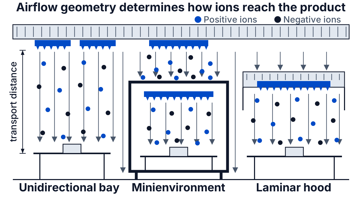
Unidirectional (laminar) flow zones
Under unidirectional flow the room is already a transport system. Air leaves the filter ceiling in a defined direction at a controlled velocity and sweeps across the work plane. Emitters mounted in or below the ceiling plenum, or bars fixed at the leading edge of the flow, inject ions into that stream and let it handle delivery. No added fan means no added turbulence and no added mechanical particle source.
The trade-off is that neutralization performance becomes a property of the installation rather than of the ionizer. Transport time is set by the ceiling-to-workplane distance and the room velocity, and ions of opposite polarity recombine along the way.
Non-unidirectional zones
In mixed or turbulent rooms there is no usable directional transport, so the ionizer must supply its own. Fan-driven blowers become legitimate again — but the fan is now the component being selected. What matters is whether the airstream passes over the electronics or through a sealed duct, what the impeller and bearings are made of, whether the discharge is filtered, and how the housing survives the facility’s wipe-down chemistry. Turbulence remains a cost even where it is allowed: a blower aimed near a settled surface re-entrains whatever is on it.
Minienvironments, tool interiors and point-of-use ionization
A minienvironment wall stops ions for the same reason it stops particles. Ions travel with air, and the enclosure exists to keep room air out. Room ionization ends at that boundary regardless of what the ceiling system is rated for. Enclosed volumes need a source inside them: a bar mounted within the tool, or ionized compressed gas where a supply already exists.
Gas-fed ionization moves the constraint to the gas. A CDA or nitrogen nozzle delivers whatever particles, moisture and hydrocarbons the line carries, at the point of use, directly onto the product, with no filter downstream. Nozzle velocity is a second constraint, since a jet strong enough to reach the surface can disturb the flow field around it.
A worked example. A carrier transfer station sits under a laminar hood in an ISO Class 5 bay, and carriers arrive charged from the transport aisle. The obvious fix, a blower on the bench, puts a fan inside the hood’s protected volume. The workable answer is a bar in the hood plenum, upstream of the work plane, so the hood’s own flow carries ions down onto the opened carrier. The bar adds ions without adding air movement. Positioning that same kind of unit on a general assembly bench, and verifying it actually covers the handling point rather than just the bench centerline, is a separate layout question, covered in our guide to where a bench-mounted ionizer belongs on a workstation.
The Ionizer as a Contamination Source
The device installed to control one failure mode introduces another. A corona ionizer contributes to the particle budget of the room it protects, through three mechanisms acting simultaneously at the same few millimeters of hardware: particles drawn from the air, particles the discharge itself generates, and material eroded from the tip.
The emitter tip sits at high potential, so it attracts charged particles out of the airstream and collects them on itself. The same discharge also generates particulate matter at the tip, and separately erodes it through oxidation and sputtering at the point of highest field. All three then leave with the airstream together — downstream of the last filter and, in a ceiling or plenum installation, directly above the product. Corona also produces ozone, which is a materials-compatibility question rather than a particle one. Material selection governs only the third of these; the particles already in the air and the particles the discharge creates persist regardless of what the tip is made of.
The direct consequence for selection is that emitter material is an ordering option, not a construction detail. Its admissibility depends on the ISO class of the installation and on the sector. Semiconductor fabs care about metallic species independently of count, because heavy metals diffuse into silicon and create defects; a particle budget that a medical device line would accept is not acceptable in a wafer fab.
The failure mode this produces is quiet. Counts drift upward in one bay over several months, and filters, tool cleans and gowning practice are reviewed in turn. The ceiling ionizer, last cleaned at an interval nobody tracked, never enters the list: it is booked as ESD equipment, and a different team audits it.
The ranking below reflects the ionizer particle-emission literature that developed from the mid-1980s onward — Liu’s characterization of cleanroom ionizers for the Institute of Environmental Sciences, Donovan’s later analysis at Research Triangle Institute in Microcontamination — together with manufacturer technical notes issued since. It is a relative ordering, not a specification.
| Emitter material | Relative particle behavior | Typical environment |
|---|---|---|
| Stainless steel | Highest reported emission; largely displaced | Legacy installations only |
| Tungsten and thoriated tungsten alloys | Lower average emission, but reported episodic bursts | Less critical ISO classes |
| Titanium | Lower still, without the reported burst behavior | General cleanroom, medical, pharmaceutical |
| Silicon and silicon-based ceramics | Lowest reported, and non-metallic | Semiconductor and other metal-sensitive processes |
Selecting the Ionization Technology
Where each corona topology fits in a cleanroom
Topology follows geometry and working distance rather than preference. Ceiling and plenum installations, where the emitter-to-product gap is measured in meters, are built on both steady-state DC and pulsed DC, so the form factor settles nothing. What separates them is how balance is held across that distance. Steady-state DC runs dedicated positive and negative emitters continuously, so balance at the work plane rests on the relative trim of two supplies whose emitters erode at different rates. Pulsed DC alternates polarity instead, extending usable coverage across a large volume while leaving an isolated conductor beneath it swinging at the pulse rate rather than holding a steady offset. AC stays short-range — inside tools, minienvironments and under hoods, at working distances of tens of centimeters, where both polarities leave the same emitter and forced airflow must deliver them before they recombine. The mechanics behind each are set out in the differences between AC, DC and pulsed DC ionizers.
Non-corona alternatives: soft X-ray and alpha sources
Soft X-ray photoionization removes all three mechanisms at once. With no energized emitter there is nothing to attract airborne particles, no corona chemistry to build a deposit, and nothing to erode — and no corona-generated ozone. No airflow is required to create ions.
Alpha sources based on polonium-210 are intrinsically balanced and need neither power nor airflow, which keeps them useful around parts with very low withstand voltages. They are rarely the default choice for administrative rather than technical reasons: a 138-day half-life means output decays continuously, so every installed point carries a licensing obligation and a recurring source renewal.
Specifications That Deserve Scrutiny
Offset voltage
ANSI/ESD S20.20 sets the ionization peak offset voltage limit at less than ±35 V in its EPA control items table, measured using ANSI/ESD STM3.1. That limit constrains the residual potential the ionizer itself can leave on an isolated conductor, which is why it tracks the 35 V isolated conductor requirement in the same standard. A manufacturer figure of ±5 V is a laboratory condition: a specified plate, a specified distance, a freshly cleaned emitter, controlled air. Field balance drifts with emitter contamination, airflow changes and mechanical shock.
The 2014 revision folded the 2007 edition’s two ionization limits — one for room ionization, one for local — into a single requirement, on the reasoning that room ionization serves cleanliness rather than ESD control and need not appear in the ESD control plan unless expressly configured for it.
S20.20 also allows a documented tailoring statement, and the standard’s own example is a pulsed DC ceiling room ionization system tailored to a peak offset of ±250 V, on the rationale that its primary function is contamination control and charge reduction on process-essential insulators. An offset figure therefore only means something alongside the zone it applies to.
Decay time and its test conditions
A decay time quoted without its distance, plate size, start and stop voltages and air conditions is not a specification. An unqualified figure is unusable for comparison, and the only values worth setting side by side are those measured under conditions resembling the intended installation. Our guide to what a charged plate monitor actually measures covers how to take that measurement correctly.
Coverage and working distance
Coverage is the specification manufacturers define most unevenly. Some quote the area over which balance stays within limits, some the area where decay stays under a target, and some a nominal geometric footprint with no performance criterion at all. The criterion that defines the edge of coverage is rarely stated, and neither is the height it applies to or the airflow it assumes — for a bar in a plenum, the coverage claim is really a claim about the room.
“Rated for ISO Class N”
ISO 14644-1 classifies the air cleanliness of rooms and zones. It does not classify equipment. A rating on an ionizer datasheet is therefore a vendor claim about the device: typically that, operated in a clean test volume, the unit did not raise particle concentration past that class limit. What makes such a claim comparable is the particle sizes counted, the sampling position and duration, the emitter material fitted and its age, and whether the unit ran at rated ion output.
ISO 14644-14 is the normative method to ask for — generic to equipment rather than corona-specific, with a size range starting at 0.1 µm, so fit to the population in question still needs checking. IEST-RP-CC022 remains a relevant reference for the request, not the equipment test method itself.
What must appear next to each specification in a quotation
- Offset voltage
- Measurement method (ANSI/ESD STM3.1, SP3.3 or SP3.4), plate size, distance, and whether the figure is peak or average
- Decay time
- Start and stop voltages, plate size, emitter distance, air condition, and both polarities
- Coverage area
- The criterion defining the edge of coverage, the working height it applies to, and the assumed airflow
- Emitter material
- The material as ordered rather than as available, plus the erosion-driven replacement interval
- Cleanliness claim
- Particle sizes counted, test configuration, sampling position and duration, and the operating state of the unit
- Maintenance interval
- The task itself, the tools and access required, and whether the zone must be shut down
- Output stability
- Whether output is closed-loop controlled, which conditions are alarmed, and what interface reports them
Maintenance as a Selection Criterion
The consumable is not the cost. An emitter point is inexpensive; the gowning, the access, the tool downtime and the requalification of the zone are not. A design that requires monthly manual cleaning of forty ceiling emitters in an operating bay has a maintenance cost that no purchase comparison based on unit price will surface.
That cost has a compliance dimension as well. A cleaning interval that the organization cannot realistically hold does not simply degrade performance; it produces a maintenance record with gaps in it, which an auditor reads as a nonconformity against the ESD control program.
This is what low-maintenance architectures are actually buying. Emitterless sources remove the cleaning task entirely and replace it with a different obligation — registration, interlocks, or scheduled source renewal. Self-cleaning designs reduce the frequency but add mechanism inside a clean space. Neither is free, and both should be evaluated against the labor and downtime they displace rather than against the price of the points they eliminate.
Closed-loop output control, fault alarming and integration with the facility monitoring system belong in the same calculation. Continuous reporting of balance drift and emitter degradation converts an unscheduled discovery into a planned intervention, which is usually where the recoverable cost sits. What that intervention consists of is set out in our guide to what a planned ionizer service involves.
Common Selection Mistakes
- A benchtop blower installed under unidirectional flow. The device works electrically and defeats the airflow design it sits inside. The ESD specification will pass; the contamination control plan will not.
- Assuming room ionization penetrates a minienvironment. The enclosure that keeps particles out keeps ions out. Enclosed volumes need their own source, sized and placed independently of the room system.
- Ignoring emitter material in a metal-sensitive process. In semiconductor environments the species matters as much as the count, and the material is chosen at order time rather than corrected later.
- Accepting a decay time without its test conditions. Two units quoting the same figure at different distances, plate sizes and air velocities are not comparable in any useful sense.
- Using ionization as a substitute for grounding. Ionization neutralizes what cannot be grounded or eliminated. Applied to conductors that could have been bonded, it adds cost and a maintenance burden without closing the actual path.
- Skipping verification after installation. Balance and decay at the work plane depend on mounting height, airflow and adjacent equipment, none of which existed when the unit was characterized at the factory.
A Practical Selection Sequence
The preceding sections resolve into a working order. Each step constrains the next, so reversing them tends to produce a device that satisfies one requirement and fails another.
- Inventory the charge sources in the zone: process insulators, isolated conductors, carriers and pods, films and webs.
- Set the offset limit from the most sensitive item handled there, and the decay time from the process tempo rather than from an available specification.
- Confirm that grounding and material substitution have already absorbed everything they can.
- Establish whether the requirement is room-wide, equipment-level or point-of-use.
- Read the airflow regime, and eliminate delivery methods that would alter it.
- Select the emitter material against the ISO class and the sector’s tolerance for metallic species.
- Choose the topology or non-corona technology that fits the geometry and working distance that remain.
- Cost the maintenance regime — access, gowning, downtime — before comparing purchase prices.
- Require the qualifying conditions listed above to accompany every quoted specification.
| Sector profile | Dominant constraint | Typical delivery method |
|---|---|---|
| Semiconductor front end | Metallic contamination at any level; large open bays | Ceiling emitters in the plenum plus point-of-use bars inside tools |
| Medical device assembly | Particle control with heavy film and adhesive handling | Bars at web and film stations; blowers where flow is non-unidirectional |
| Pharmaceutical filling and packaging | Regulated environment, cleanability, material compatibility | Bars integrated into equipment, with wipe-down-tolerant construction |
| Battery dry rooms | Very low humidity extending charge retention; large enclosed volumes | Wide-area bar or ceiling ionization sized to the volume |
| Optical and hard disk assembly | Extremely low tolerated residual voltage on exposed parts | Close-proximity bars or intrinsically balanced sources at the work point |
Frequently Asked Questions
Can a benchtop ionizing blower be used in a cleanroom?
Only in non-unidirectional zones, and only if the fan and enclosure are built for the class. Under unidirectional flow the fan disrupts the airflow pattern the room depends on. A bar or ceiling emitter using the existing airflow is the appropriate choice.
Does an ionizer generate particles?
A corona ionizer can. The emitter attracts charged particles electrostatically, generates new particulate matter in the discharge, and erodes under it — all three release into the airstream downstream of the final filter. Emitter material and cleaning discipline determine how much. Soft X-ray and alpha sources have no eroding emitter.
Is ionization still needed if the room already has dissipative flooring and grounded workstations?
Usually yes. Grounding only controls objects with a conductive path to ground. Process insulators and isolated conductors keep their charge regardless of flooring, and in a cleanroom those items — carriers, film, packaging — are often the dominant charge sources.
What does an 'ISO Class 5 rated' ionizer specification actually mean?
It is a claim about the device, not the room. ISO 14644-1 classifies air cleanliness in rooms and zones, not equipment. The vendor is stating that under some defined test the unit did not push particle concentration past that class limit. Ask for the method — ISO 14644-14 is the normative one.
Does room ionization reach inside a minienvironment?
No. A minienvironment wall stops ions for the same reason it stops particles: ions are transported by air, and if the air does not enter, neither do they. Enclosed volumes need their own bar, gas-fed nozzle or non-corona source inside.
How often do cleanroom ionizer emitters need cleaning?
It depends on emitter material, ion output and the cleanliness of the surrounding air, so the interval is set by observed performance drift rather than a fixed rule. Treat the manufacturer's stated interval as a starting point and confirm it is achievable in your gowning regime.
Related articles
Electronics25 min read
ESD Workstation Setup: Grounding, Layout and Assembly
How the elements of an ESD workstation bond to a common point ground, where each one belongs on the bench, and what layout mistakes survive a component check.
Electronics14 min read
ESD Ionizer Maintenance: Cleaning, Service, and What a Failed Check Means
A failed charged plate monitor reading is a maintenance trigger. How to localize the fault, clean and service an ESD ionizer, and know when cleaning is no longer the answer.
Electronics13 min read
How to Test an ESD Ionizer with a Charged Plate Monitor
Offset voltage has a fixed limit; discharge time does not. How to run a charged plate monitor check, read the result, and know which standard applies.
Electronics15 min read
ANSI/ESD S20.20: How an ESD Control Program Is Defined, Qualified and Verified
How ANSI/ESD S20.20 defines an ESD control program, what product qualification establishes, and how compliance verification keeps it demonstrable.