How to Test an ESD Ionizer with a Charged Plate Monitor
Offset voltage has a fixed limit; discharge time does not. How to run a charged plate monitor check, read the result, and know which standard applies.
By YDT EditorialUpdated 13 min read
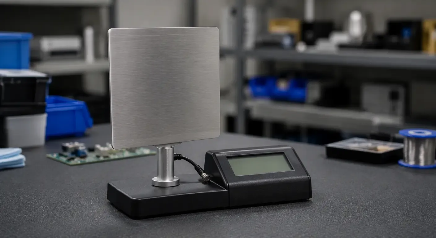
An ionizer has been running over a workstation for months, a charged plate monitor sits on the bench beside it, and the instrument returns two numbers. Neither means anything until you know what to compare it against.
That comparison is where periodic checks go wrong. One of the two readings has a limit written into the program standard the facility is audited against. The other has no external limit at all: no standard on this path prescribes a discharge time, so any figure used is one the site established for itself. Treating both as if they came from the same place produces a record that passes a check it should have failed, or fails one that was never out of tolerance.
What follows is the measurement itself — which document answers which question, how the plate is placed and zeroed, what makes a reading wrong rather than merely poor, and what the record has to contain. It assumes you already know what an ESD ionizer does. It is one part of the complete ESD control and cleanroom guide.
What a Charged Plate Monitor Actually Measures
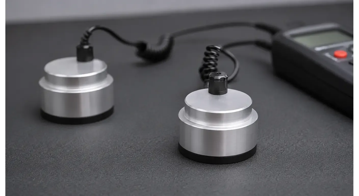
The instrument does one physical thing: it raises an isolated conductive plate of known capacitance to a set potential, releases it, and watches what the surrounding air does to that potential.
The plate is a stand-in, not your device
The plate stands in for the isolated conductors that matter in production — a lead frame in a carrier, a floating shield, a board held in a fixture. It substitutes for them because its capacitance is defined and stable, not because it resembles anything. Nothing measured on the plate transfers directly to a device with a different capacitance. What transfers is the statement that the air at that point removes charge, and the potential at which it leaves the plate sitting.
Two readings, two failure modes
Decay and offset fail independently, and each has its own cause. An ionizer can neutralize a charged plate quickly and still hold it tens of volts away from ground; it can sit perfectly on balance and take far too long to get there. Reporting a single verdict for the two collapses information the record needs. On pulsed emitters the offset of interest is a peak within a swing rather than a steady value — the distinction is developed in the discussion of peak offset voltage on pulsed DC ionizers and is assumed here.
Which Document Answers Which Question
Four designations circulate around this measurement, and they do not answer the same question.
Two documents already draw the line
That separation is already established: a test method characterizes an ionizer as a device, while a periodic verification follows what happens to it in service — the reasoning is set out where how test methods and periodic verification differ is treated in full. The table below places the remaining designations against the question each one answers.
| Question being asked | Designation | Nature of the evidence |
|---|---|---|
| Does this ionizer perform as its type is specified to? | ANSI/ESD STM3.1 | Characterization of a device under defined test conditions |
| Is the installed unit still doing its job? | ESD TR53 | Confirmation that a basic function is present, in place |
| Is the balance moving between checks? | ANSI/ESD SP3.3 | A trend, tracked over successive readings |
| Can a small enclosure be checked at all? | ANSI/ESD SP3.4 | A method for confined spaces, distinct from the full-size plate |
Where compliance verification stops
Compliance verification confirms that a function is present. It does not establish a measurement capability, and it does not qualify the equipment against its type specification. A passing periodic check is evidence the ionizer is still working; it is not evidence that it still meets the figures it was selected on. Those two claims are frequently written into the same line of a log, and only one of them is supported.
Confined spaces and small fixtures
Where a full-size plate cannot physically be placed — inside a small enclosure, a nest, a confined fixture — SP3.4 exists as a separate method. It is a different method rather than a relaxed version of the same one, and its results are not interchangeable with those from a full-size plate. A record that mixes the two across successive checks has no trend in it.
The Limits Are Not Symmetrical
Half of this verification has an external criterion. The other half does not, and the asymmetry is the single most useful thing to understand before recording a result.
The offset limit comes from the program standard
The offset limit for ionization is normative. It appears in the EPA control items table of ANSI/ESD S20.20 as less than ±35 V, and the method by which that offset is obtained is ANSI/ESD STM3.1. Two documents are therefore in play for one number: one states the limit, the other states how it is measured. A reading taken by some other method may be useful engineering information, but it does not demonstrate conformity to that limit. How the surrounding requirements are structured is covered in the treatment of how a control program is qualified and verified.
The discharge time limit comes from you
No standard on this path prescribes a discharge time. The program standard requires that a limit exist and that the equipment be verified against it; it does not supply the figure. That figure is established at acceptance, on the installed unit, at the real working distance and in the real position — not read from a datasheet, since the manufacturer’s laboratory figure is obtained under conditions the workstation does not reproduce.
The practical consequence is that a discharge time can only fail against your own baseline. An installation with no baseline has no failing condition for half its verification, however diligently the readings are logged. Establishing that baseline is not paperwork ahead of the measurement; it is the measurement that makes every later one interpretable.
Making the Measurement
Everything below assumes the plate has been placed where the work actually happens, at the distance the protected items actually sit.
Plate position, orientation and grounding
Orient the plate face as the protected surface is oriented: a plate turned toward the emitters when the work lies flat measures a geometry that does not exist in production. Ground the monitor chassis to the same ground the workstation uses, not to a convenient nearby structure. Keep hands, sleeves and grounded fixtures away from the plate during decay. A grounded conductor brought close to the plate raises its effective capacitance, and decay time scales with capacitance — so the reading lengthens, and the ionizer is blamed for an obstruction the operator introduced.
Zeroing outside the ion field
Establish the instrument zero with the plate out of the ion field, or with the ionizer off. A zero taken inside the field subtracts the ionizer’s own offset from every subsequent reading, which is exactly the quantity being measured. This produces the most convincing wrong result available on this instrument: a balanced unit, reported by an instrument that was told the field was zero.
Both polarities, every time
Charge the plate positive, record the decay and the settled offset, then charge it negative and repeat. Both polarities are required because the failure being looked for is one-sided: emitter wear, contamination and drive imbalance rarely affect positive and negative output equally. An average across the two polarities can sit comfortably inside limits while one direction is well outside them. The slower polarity is the result; the average is not a result at all.
The coverage area is not a point
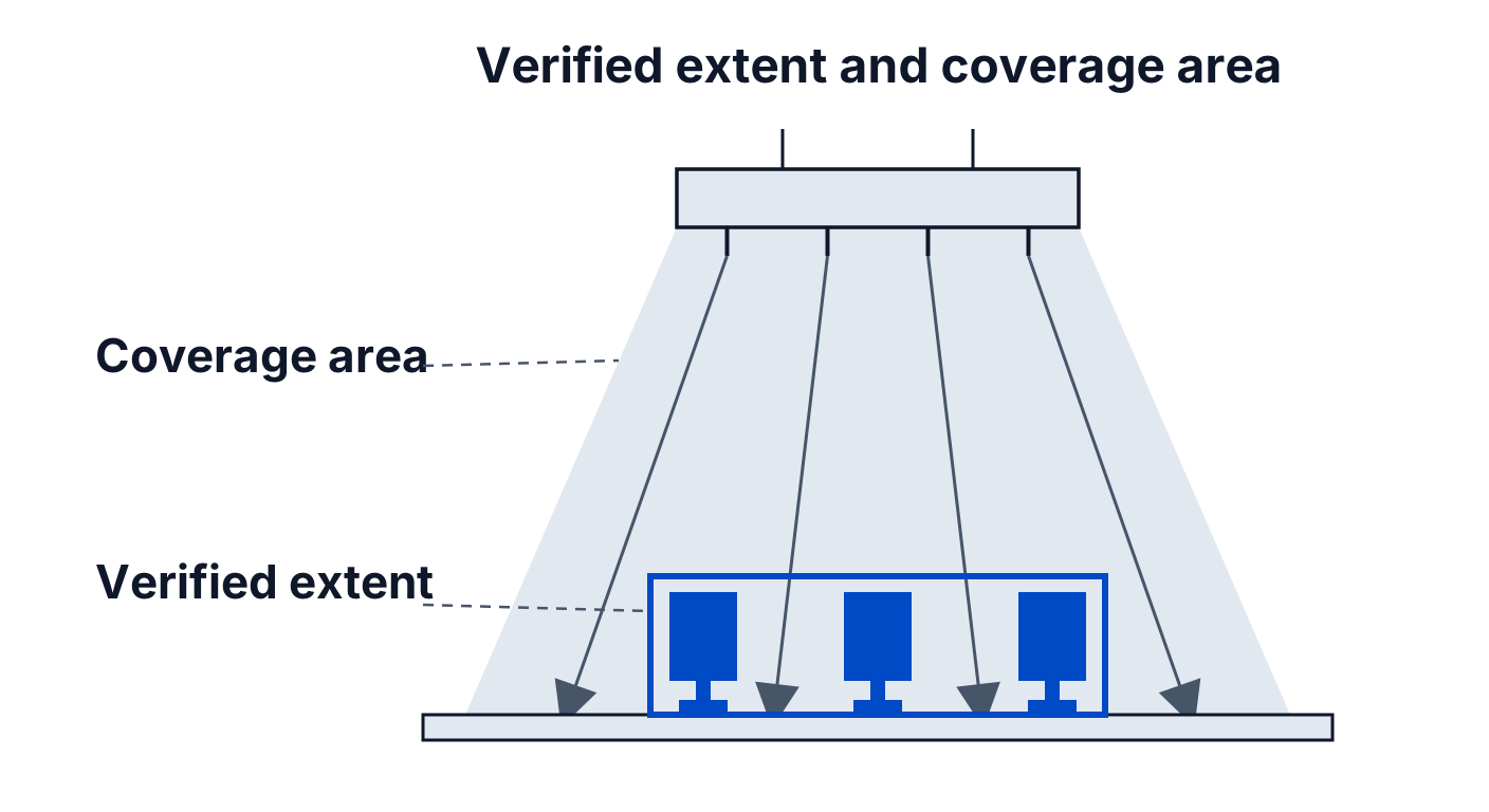
An ionizer is specified over an area, but a plate reads one position. The volume in which charge is actually neutralized is bounded by airflow, by the obstacles on the bench and by the height at which the work sits — and it is routinely smaller than the area quoted for the unit. Sample several positions across the working surface, including the corners furthest from the emitters and any position shadowed by equipment, at the height the parts occupy. Then record what was sampled. A verified installation is the set of positions where the plate was actually placed, and nothing outside it has been demonstrated.
What Makes a Reading Wrong
An out-of-tolerance result has two possible origins: the ionizer, or the measurement. Genuine degradation is real and has known causes — emitter condition and particle generation track together as emitters age. Acting on it once it is confirmed is covered in how an ionizer is serviced after a failed check. This section is about the other origin, where the ionizer is fine and the reading is not trustworthy.
Instrument drift against a ±35 V limit
The offset limit is a band of ±35 V, and the instrument judging it has a zero of its own that moves. If the monitor’s zero wanders by a meaningful fraction of that band over the duration of a check, the reading cannot separate a pass from a fail, and neither result carries information. Allow the instrument to reach thermal stability before the first reading, re-establish zero between positions rather than once at the start, and treat a zero that has visibly moved during a sequence as invalidating that sequence rather than as a correction to apply afterwards.
Plate capacitance is a verified property
Decay time depends on the plate’s capacitance. A plate whose capacitance is not the value the instrument assumes returns a decay time wrong by a proportional factor — and a proportional error is the hardest kind to notice, because the number stays entirely plausible. This is why plate capacitance is a verified property of the instrument rather than a nominal figure: the test method carries a normative procedure for measuring it. A monitor whose plate has been damaged, remounted or contaminated at its insulators no longer has the capacitance its calibration assumed, whatever the label on it still says.
Contact and non-contact plates do not read alike
Instruments differ in how the plate is charged and how it is isolated at release. Those differences change both the initial condition and the leakage path, and they produce readings that are internally consistent but not comparable across instrument types. Establish the baseline and run the subsequent checks with the same type of instrument. Where a monitor is replaced with one of another type, the trend restarts — the new instrument’s first reading is a baseline, not a data point in the old series.
A small fixture is not a CPM
A handheld verification fixture carries a small plate with a different capacitance and samples a much smaller portion of the field. It is a screening tool for confirming that an ionizer is still emitting, and its readings sit outside the series the record is built from. A simplified kit can also miss a peak excursion entirely, which is a known limitation rather than a fault of the individual unit.
The Record That Survives an Audit
What makes a verification defensible is not the numbers themselves but whether a later reader can tell what they were compared against.
Baseline first, comparison after
The baseline is established once, at acceptance, on the installed unit in its real position, and it records more than two figures: the sampled positions and their height, the plate orientation, the working distance, the instrument identity, and the result for each polarity at each position. Every later check is a comparison against that record. Its value grows with time, because the quantity actually being watched is balance drift once an ionizer is in service rather than any individual reading.
What a documented deviation contains
A deviation is not a failed line in a log. It states what was measured, at which position, with which instrument, against which baseline, by how much the result differed, what was decided, and on what technical basis. A deviation recorded with its reasoning survives review; a bare failure followed by a passing retest reads as a measurement someone repeated until it agreed with them.
Frequently Asked Questions
What offset voltage is acceptable for an ionizer?
The EPA control items table of ANSI/ESD S20.20 sets the offset limit at less than ±35 V, measured by the method of ANSI/ESD STM3.1. A process may impose something tighter, and a manufacturer figure such as ±5 V describes laboratory conditions rather than an installed workstation.
Is there a standard discharge time limit?
No. None of the documents on this path prescribes a discharge time. The program standard requires that a limit exist and that the equipment be verified against it, but the figure comes from the baseline your site established on the installed unit, in its real position.
How often should ionizer performance be verified?
No standard on this path prescribes a frequency. The interval belongs to the compliance verification plan, where it is set from the criticality of the process, the stability observed in the record and the type of ionizer installed.
Can a portable verification kit replace a charged plate monitor?
No. A portable kit carries a smaller plate of different capacitance and samples a smaller portion of the field, and it can miss a peak excursion altogether. It is useful for confirming that a unit is still emitting between scheduled checks, and its readings do not belong in the same series.
What does a failed reading indicate?
An offset outside the band indicates imbalance between the positive and negative output. A decay time longer than the baseline indicates reduced ion delivery at that position. Both together indicate that output and balance have moved at once. Identifying the cause and correcting it is a separate exercise from the verification.
Related articles
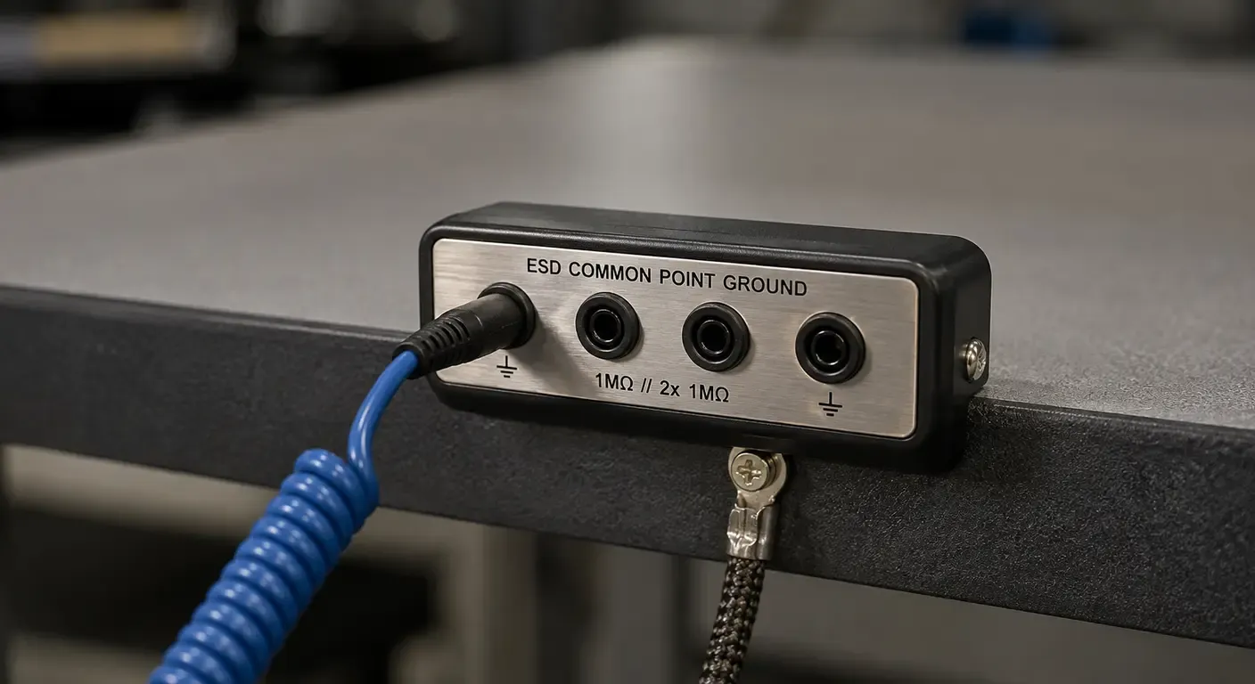
Electronics25 min read
ESD Workstation Setup: Grounding, Layout and Assembly
How the elements of an ESD workstation bond to a common point ground, where each one belongs on the bench, and what layout mistakes survive a component check.
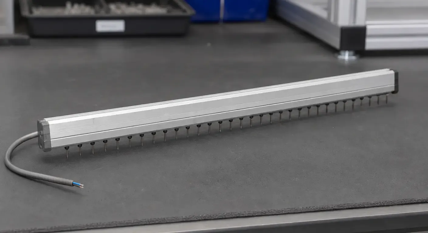
Electronics14 min read
ESD Ionizer Maintenance: Cleaning, Service, and What a Failed Check Means
A failed charged plate monitor reading is a maintenance trigger. How to localize the fault, clean and service an ESD ionizer, and know when cleaning is no longer the answer.
Electronics15 min read
ANSI/ESD S20.20: How an ESD Control Program Is Defined, Qualified and Verified
How ANSI/ESD S20.20 defines an ESD control program, what product qualification establishes, and how compliance verification keeps it demonstrable.

Electronics17 min read
ISO 14644: How Cleanroom Classification Works
What an ISO 14644 class number actually asserts, how a classification is demonstrated and kept valid, and where the series deliberately stops.