AC vs DC vs Pulsed DC Ionizers: How Do They Compare?
AC vs DC vs pulsed DC ionizers compared: how each generates ions, what separates them on decay time and balance, and why test conditions govern the numbers.
By YDT EditorialUpdated 18 min read

Grounding takes care of conductors that can be grounded. Everything else — an isolated conductor sitting on a fixture, a polymer tray, a reel of carrier tape feeding a placement machine — needs air ions. That is why ionizers appear in almost every ESD protected area and in nearly every cleanroom handling sensitive devices.
What receives far less attention is how those ions are produced. Corona ionizers are built on three distinct architectures: AC, steady-state DC, and pulsed DC. They differ in how the two polarities are generated and delivered to the target, and those differences propagate directly into discharge time, balance stability, useful reach, and how heavily the device depends on forced airflow.
This article covers how each topology works, what separates them on measurable quantities, and which parameters deserve evaluation before a selection is made. It is one part of the complete ESD control and cleanroom guide.
Why Ionization Topology Matters
An ionizer floods the surrounding air with positive and negative ions so that charge on surfaces grounding cannot reach is neutralized by attraction of the opposite polarity. The corona mechanism itself, the distinction between grounding and ionization, and the main equipment formats are covered in the guide to what an ESD ionizer is and how corona ionization works.
Form factor and topology are two independent axes, and conflating them is a common source of confusion. Benchtop, overhead, nozzle and bar describe where the ionizer sits and how it directs ions toward the work. AC, steady-state DC and pulsed DC describe how the high-voltage supply drives the emitters. A benchtop unit can be built on any of the three, and so can an overhead bar.
The second axis is what governs performance, and it does so through two measurable quantities.
The Two Metrics That Govern the Comparison
Decay time is the interval an ionizer needs to neutralize a known charge on an isolated conductor. The reference protocol charges a plate on a charged plate monitor and measures the time taken to fall from 1,000 V to 100 V, in both polarities. ANSI/ESD STM3.1 and IEC 61340-4-7 define the measurement technique and the test conditions under which it is performed.
The number means very little on its own. Decay time is a function of distance from the emitters, air velocity, initial charge, plate geometry and fixture position. A figure obtained at close range with air assist at full output describes an operating point, not a property of the device.
Offset voltage — ion balance — is the residual potential an isolated conductor reaches when it is simply left exposed to the ionizer. If the device delivers slightly more positive than negative ions, an isolated conductor does not converge on 0 V; it converges on some positive potential, and the ionizer has become a charging source rather than a neutralizing one. ANSI/ESD S20.20 sets the peak offset voltage limit at less than ±35 V for ionization used within an EPA, measured by the STM3.1 method.
The two quantities are not independent, and no architecture optimizes both without a compromise somewhere. Each section that follows describes what a given topology does to decay time and what it costs in balance.
AC Ionization
A benchtop ionizer neutralizes reliably when the work sits directly beneath it at short range. Move the same work further away — a larger fixture, an operator who shifted the tray, a taller carrier — and discharge times lengthen to the point where the unit contributes almost nothing. Nothing has failed. The mechanism has simply run out of range.
How it works
An AC ionizer drives a single set of emitters from an alternating high-voltage supply, generally at line frequency. Each emitter produces positive ions during one half cycle and negative ions during the next. One emitter set, both polarities, no relative trim between two independent supplies.
Where the mechanism limits it
The limitation is temporal. At 50 Hz or 60 Hz, a half cycle lasts roughly 8 to 10 ms. Ion transit to the target takes far longer than that: assuming an assist airflow on the order of 1 m/s, 300 mm of travel takes about 0.3 s, which spans tens of half cycles. Long before the first population of positive ions arrives, the same emitter has been producing negative ions into the same volume of air.
The two populations therefore coexist along the entire path and recombine on the way to the surface. Recombination in an AC ionizer is structural, not a defect of a particular implementation.
Three consequences follow. Useful reach is the shortest of the three architectures. Forced airflow is normally required rather than optional, because ions have to be carried out of the mixing region faster than they neutralize each other. And decay time degrades steeply with distance, which is why an AC unit can look excellent on a bench measurement and disappoint at the real working height.
One further consequence belongs with them. Because polarity alternates, an isolated conductor under an AC ionizer does not settle at a fixed potential either — it oscillates at line frequency. That behavior is taken up alongside pulsed DC, where the same mechanism becomes a design variable rather than a fixed property of the supply.
Where AC fits
The architecture is simple, mature and inexpensive to build and maintain. A single emitter set erodes under both polarities rather than one, which removes the differential wear problem discussed in the next section. Both polarities are continuously available, so a target whose charge polarity is unknown or alternating is handled without configuration. Where the working distance is short and the process tolerates air movement, an AC ionizer is a sound engineering answer. The trade-off is a strong and permanent coupling between airflow and performance.
Steady-State DC Ionization
An ionizing bar installed above a cleanroom transport line passes verification at commissioning. Some months later, a technician measuring at several points along its length finds balance well controlled at one end and drifting positive at the other. The bar has not been damaged, and nothing in the room has changed.
How it works
A steady-state DC ionizer uses dedicated emitters for each polarity, each driven by its own continuously energized supply — one positive, one negative. There is no alternation, so there is no cycle-driven mixing at the emitter itself.
Where the mechanism limits it
Recombination does not disappear; it relocates. The two ion clouds are produced at separate points, but they still meet in the space between and beyond the emitters, and where they overlap they neutralize one another. Because generation is continuous and the sources are spatially separated, a larger fraction of each polarity survives to reach a distant target than in an AC device. Reach improves accordingly.
The cost appears in balance. Offset voltage in a DC ionizer is set by the relative output of two independent supplies, so any asymmetry between them shows up directly as residual potential on an isolated conductor. Worse, the asymmetry does not stay put. Positive and negative emitters do not erode or accumulate contamination at the same rate, because the physical processes at a positive and a negative corona point differ. Balance therefore drifts with service hours, and along a long bar it drifts unevenly, since local airflow and contamination differ from one end to the other. That is the drifting bar in the opening paragraph.
Where DC fits
Steady-state DC suits installations needing greater working distance than AC can support, and processes where air velocity has to be limited for reasons unrelated to ESD. What it demands in return is a maintenance regime: emitter cleaning on a defined schedule, periodic balance verification at multiple points rather than one, and re-trimming treated as a routine task rather than a corrective action.
Pulsed DC Ionization
An ionizer passes its periodic charged plate monitor check comfortably. Offset voltage sits well inside limits and decay time is unchanged from commissioning. Yet CDM-attributed failures keep appearing at that station. The verification is not wrong — it is answering a different question from the one the failures are asking.
How pulsed operation works
A pulsed DC ionizer also uses dedicated emitters per polarity, but energizes them alternately rather than continuously: a burst of positive ions, then a burst of negative ions, at a rate that is normally adjustable by the user. The two clouds are separated in space, as in steady-state DC, and additionally separated in time.
The frequency trade-off
That separation in time is the entire design idea, and it is a trade-off with no free side.
At a low pulse rate, the bursts are widely spaced. A burst has largely cleared the emitter region before the opposite polarity is generated, so recombination in the intervening air falls and a larger fraction of each burst survives the journey. Reach increases and dependence on forced air decreases. But the target now sees an interval of predominantly positive charge followed by an interval of predominantly negative charge, and its potential swings further in each direction between bursts.
At a high pulse rate the picture inverts. The bursts overlap in the air, recombination climbs, reach falls, and the device begins to behave more like an AC ionizer. What improves is behavior at the target: the excursions are smaller and faster, and the potential of an isolated conductor stays closer to zero at every instant.
Frequency is a genuine design variable available to the user, which distinguishes pulsed DC from AC, where the alternation rate is fixed by the supply and airflow is the only meaningful adjustment.
Balance oscillation and what it means for sensitive devices
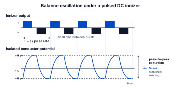
Under a pulsed ionizer, an isolated conductor does not settle at 0 V. It oscillates around 0 V at the pulse rate, and the amplitude of that oscillation depends on the pulse frequency and on the distance to the emitters. Steady-state DC does not produce this behavior. AC does, at line frequency.
ANSI/ESD STM3.1 accounts for it: for a pulsed DC ionizer the standard defines peak offset voltage as the maximum plate potential, not a settled average. The gap is therefore not in the standard but in practice. A charged plate monitor that reports only a stabilized reading, or a simplified periodic-verification kit of the kind ANSI/ESD SP3.3 describes, can return a comfortable offset figure while the plate is swinging well beyond it. Balancing a pulsed installation requires an instrument that resolves peak positive and negative excursions.
For most assembly work that is acceptable, because the excursions are modest relative to the withstand voltage of the parts being handled. For a device sensitive to charged device model events, which may be contacted at any arbitrary point in the cycle, a settled average is not the relevant quantity. The peak excursion is.
Three-Way Comparison
The three architectures differ on a small number of dimensions that actually separate them. Characteristics that behave identically across all three have been left out.
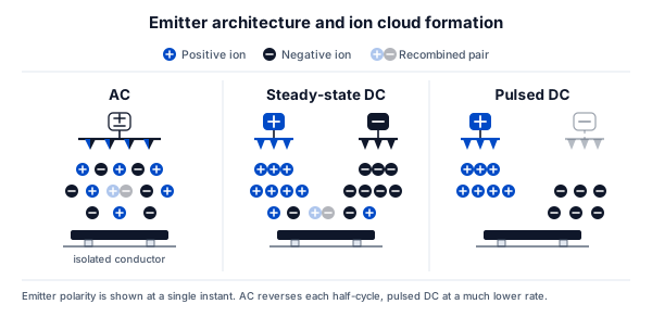
Architectural differences between AC, steady-state DC and pulsed DC corona ionizers.
| Characteristic | AC | Steady-state DC | Pulsed DC |
|---|---|---|---|
| Ion generation | Alternating polarity from a shared emitter set at line frequency | Both polarities generated continuously and simultaneously | Polarities generated in alternating bursts at a selectable rate |
| Emitter configuration | One emitter set producing both polarities | Dedicated positive and negative emitters, permanently energized | Dedicated positive and negative emitters, alternately energized |
| Dominant ion loss mechanism | Recombination along the whole path, both polarities sharing the same air | Recombination where the two spatially separated clouds overlap | Recombination between successive bursts, increasing with pulse rate |
| Balance behavior | Oscillates at line frequency; mean value governed by waveform symmetry and emitter condition | Governed by relative trim of two supplies; drifts with differential emitter wear | Oscillates around zero at the pulse rate; amplitude widens as the rate falls |
| User-adjustable parameter | Airflow only | Relative output of the two supplies | Pulse frequency, plus relative output |
| Airflow dependence | High; forced air normally required to outrun recombination | Moderate; useful reach without heavy air assist | Lowest at low pulse rates, rising toward AC behavior as the rate increases |
| Relative useful reach | Shortest, degrading steeply with distance | Greater than AC at comparable airflow | Greatest at low pulse rates, converging toward AC at high rates |
| Maintenance complexity | Lowest; single emitter set, symmetric wear | Higher; asymmetric emitter erosion and periodic re-balancing | Highest; emitter maintenance plus frequency and balance settings to re-verify |
Ion recombination
Recombination is the mechanism behind every reach figure in the table, but its cause differs in each case. In AC it is temporal: both polarities occupy the same air because they come from the same emitter within a few milliseconds of each other. In steady-state DC it is spatial: the clouds are separated at the source but converge downstream. In pulsed DC it is a function of the operating point, rising and falling with the frequency setting. Reach is not a fixed attribute of a topology — it is what remains after recombination has taken its share.
Airflow dependence
Ions must physically travel from emitter to surface, and natural convection alone transports them slowly and unpredictably. Forced air shortens transit time, which reduces recombination losses and extends useful range, and it is the reason AC ionizers are almost always air-assisted.
The cost is mechanical. A workstation handling 0201 passives or thin film will see parts move before the airflow reaches the velocity that makes an AC ionizer perform well. Architectures that reach further at lower air velocity relieve that conflict, which is often the real reason a DC or pulsed design is selected — not the decay time, but the air velocity it allows the process to run at.
Cleanroom compatibility and contamination
Corona emitters erode. Material is removed from the emitter tip and can be released into the airstream, and contamination deposited on the tip changes both discharge behavior and balance. In a classified environment the relevant questions are the emitter material, the particle generation measured under representative conditions, and how the cleaning procedure fits the room’s operating discipline.
No topology is cleanroom-safe by nature. Compatibility depends on the ISO 14644-1 class being maintained, the emitter material, the way the unit is integrated into unidirectional airflow, and the maintenance regime actually applied. An architecture that performs well electrically can still be the wrong choice if its emitters require frequent manual cleaning inside a running room.
Matching Technology to Application
| Context | What governs the choice |
|---|---|
| General ESD workstation | Working distance and coverage area, then how much air movement the process will tolerate |
| Cleanroom | Particle generation, emitter material and cleaning regime, ahead of electrical performance |
| Semiconductor and MEMS handling | Amplitude of the balance swing, not a single stabilized offset reading |
| Large-area or conveyor installation | Installation geometry and ion transport over the required distance |
| Highly CDM-sensitive components | Instantaneous balance behavior at the moment of contact |
None of these rows selects a topology on its own; each one identifies the constraint that should be resolved first, because it usually eliminates one or two architectures before any performance figure is examined.
One conclusion holds across all of them: the shortest decay time is not automatically the right answer. An ionizer that neutralizes quickly but sits outside its balance limit deposits charge continuously on the devices it was installed to protect, while a slower but stable unit merely takes longer to help.
Verifying Performance in Your Own Environment
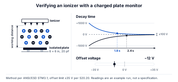
The charged plate monitor is the reference instrument. A plate of defined dimensions and capacitance is charged to a known potential and its decay observed; the same instrument, with the plate left floating, reads the offset voltage the ionizer imposes on an isolated conductor.
ANSI/ESD STM3.1 and IEC 61340-4-7 define the test methods used to evaluate and select ionizers. ANSI/ESD SP3.3 addresses periodic verification of ionizers already in service, using simpler and more portable instrumentation than full qualification requires. The documents serve different purposes: one characterizes a device, the other tracks its drift over time. Our guide to how ionizer performance is verified with a charged plate monitor covers the procedure itself.
Neither substitutes for measurement at the point of use. Two ionizers advertising very different decay times often behave almost identically once installed, because the published figures came from different distances and different airflow conditions. The only measurement that commits you is the one taken at your working distance, in your airflow, with your fixture in place.
Corona ionization is also not the whole field: soft X-ray and radioisotopic sources are used in some semiconductor applications for their absence of particle generation and inherently near-zero offset, and they fall outside the scope of this comparison.
Frequently Asked Questions
What is the difference between AC and DC ionizers?
An AC ionizer generates both polarities at the same emitters, alternating at line frequency. A steady-state DC ionizer uses dedicated emitters for each polarity, energized continuously. The practical consequence is recombination: in AC both polarities share the same air from the outset and neutralize each other en route, which shortens useful reach and makes forced airflow effectively mandatory.
Does pulsed DC always outperform AC ionization?
It depends which parameter is being optimized. Pulsed DC generally reaches further at lower air velocity, which matters for large coverage areas or airflow-sensitive processes. Both alternate polarity, so both leave an isolated conductor oscillating rather than settled; on a pulsed unit the rate is selectable, which turns the amplitude into a design variable rather than a fixed consequence, and it adds electronic complexity, cost and settings that must be verified after maintenance.
Which ionization technology is best for cleanrooms?
No topology is inherently cleanroom-compatible. Suitability depends on the ISO class being maintained, the emitter material and its erosion behavior, particle generation measured under representative conditions, integration with unidirectional airflow, and whether the required cleaning procedure is realistic inside a running room. Those criteria should be settled before electrical performance is compared.
What does ion balance actually measure?
Ion balance, reported as offset voltage, is the residual potential an isolated conductor reaches when exposed to the ionizer. A perfectly balanced device drives it to zero. An unbalanced device drives it to a non-zero potential, meaning the ionizer is charging the target rather than neutralizing it. ANSI/ESD S20.20 sets the peak offset voltage limit at less than ±35 V within an EPA.
Why can't I compare manufacturers' discharge times directly?
Because decay time is a property of a measurement setup, not of a device. Distance to the plate, air velocity, initial charge and fixture geometry all change the result, and the test standards deliberately allow those conditions to be adapted. Unless two figures were obtained under identical conditions, comparing them compares test setups rather than ionizers.
Conclusion
Use the priority that constrains your process hardest as the entry point:
| Priority requirement | Where to start investigating |
|---|---|
| General ESD control | AC or steady-state DC, decided by working distance and coverage area |
| Tight, stable balance | Compare steady-state DC against pulsed DC on measured offset, not on architecture |
| Highly sensitive components | Evaluate the amplitude of the balance swing rather than a single stabilized reading |
| Cleanroom installation | Contamination behavior and airflow integration before electrical performance |
| Large-area coverage | Installation geometry and ion transport distance first |
These are starting points for investigation, never prescriptions. Topology narrows the field; the measurement made in your own environment, at your own working distance, is what decides.
For a cleanroom installation specifically, topology is only one input among several that pull in different directions — our guide on how to choose an ionizer for a cleanroom covers the rest, from airflow delivery to emitter material and contamination control.
Related articles
Electronics25 min read
ESD Workstation Setup: Grounding, Layout and Assembly
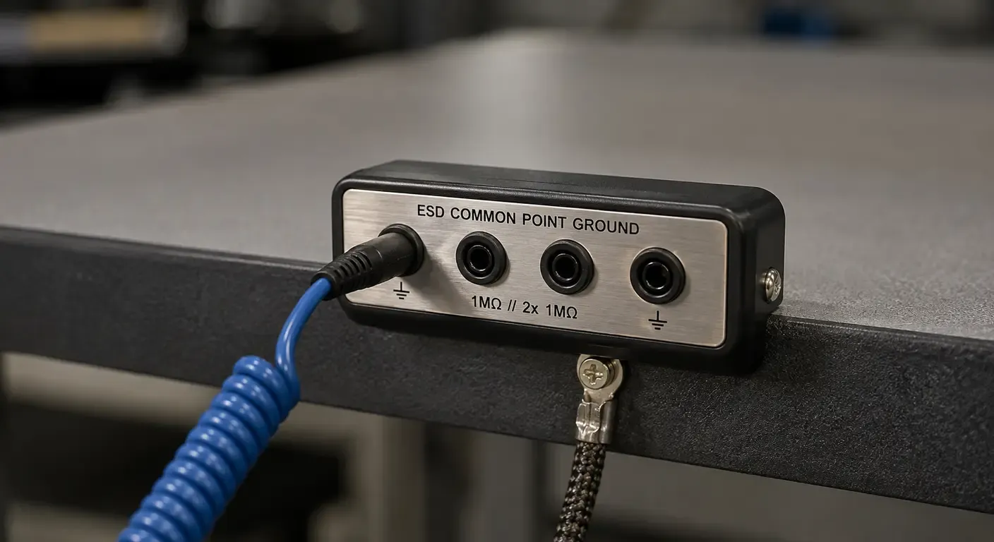
How the elements of an ESD workstation bond to a common point ground, where each one belongs on the bench, and what layout mistakes survive a component check.
Electronics14 min read
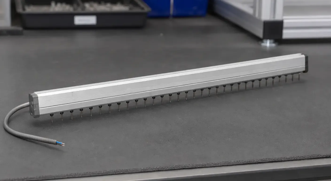
ESD Ionizer Maintenance: Cleaning, Service, and What a Failed Check Means
A failed charged plate monitor reading is a maintenance trigger. How to localize the fault, clean and service an ESD ionizer, and know when cleaning is no longer the answer.
Electronics13 min read
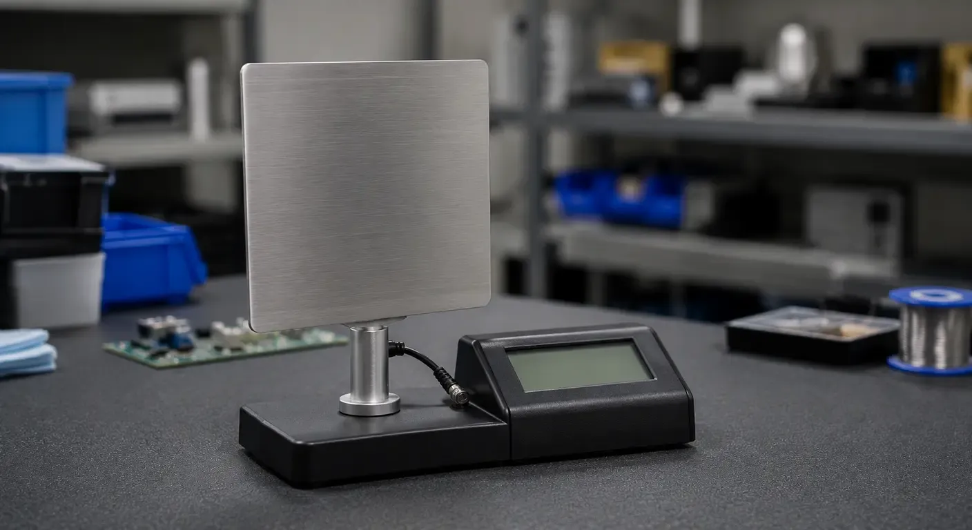
How to Test an ESD Ionizer with a Charged Plate Monitor
Offset voltage has a fixed limit; discharge time does not. How to run a charged plate monitor check, read the result, and know which standard applies.
Electronics15 min read
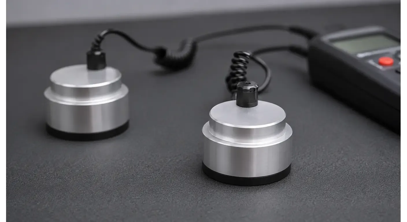
ANSI/ESD S20.20: How an ESD Control Program Is Defined, Qualified and Verified
How ANSI/ESD S20.20 defines an ESD control program, what product qualification establishes, and how compliance verification keeps it demonstrable.