Oscilloscope Triggering Explained: How to Capture Stable Waveforms
Learn how oscilloscope triggering works, including edge, pulse, slope and video triggering, trigger level, holdoff and practical tips for capturing stable waveforms.
By YDT Editorial26 min read
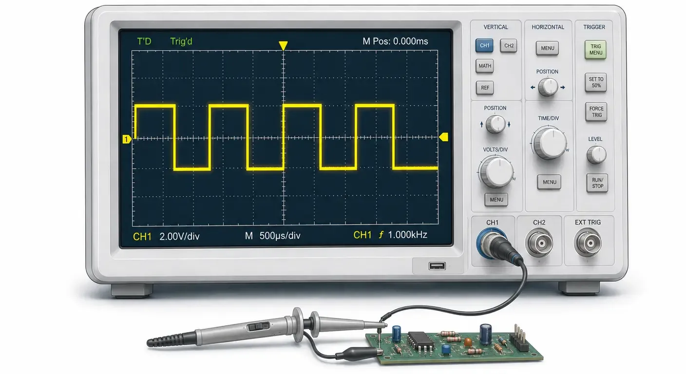
A waveform that refuses to hold still on screen is rarely caused by a faulty signal or a defective instrument. In most cases it is a triggering problem. Triggering is the mechanism that decides when an oscilloscope captures a waveform, and it is what turns a continuous stream of samples into a stable, readable display.
This guide explains oscilloscope triggering from first principles: what the trigger circuit does, how trigger source, level and slope interact, when to use Auto, Normal or Single mode, and how holdoff and specialized trigger types solve problems that basic edge triggering cannot. The concepts apply to any modern digital oscilloscope, regardless of manufacturer or price class.
If you are still building your foundation, start with our guide to what an oscilloscope is and how it works, then return here. For where triggering sits among the other instrument specifications, see our complete Test & Measurement guide.
What Is Oscilloscope Triggering?
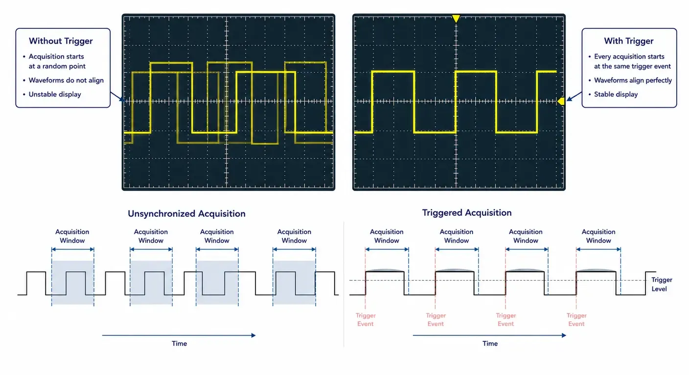
Oscilloscope triggering is the process of starting a waveform acquisition when the input signal meets a defined condition, such as crossing a specified voltage on a rising edge. By referencing every acquisition to the same signal event, the oscilloscope draws repetitive waveforms in the same horizontal position, producing a stable display instead of a moving one.
Why a waveform appears unstable
An oscilloscope acquires a finite window of a continuous signal, then repeats. Without a common reference, each acquisition begins at an arbitrary point in the signal’s period.
The result is a set of overlapping traces, each displaced horizontally from the last. On screen this appears as a waveform that scrolls, flickers, or blurs into an unreadable band. The signal itself may be perfectly stable and periodic; what is missing is synchronization between the signal and the acquisition system.
How triggering synchronizes waveform acquisition
The trigger circuit continuously monitors a selected signal and compares it against a user-defined trigger condition. When that condition is satisfied, it generates a trigger event, and the acquisition system marks that instant as the reference point of the waveform record.
Because the reference point corresponds to the same feature of the signal on every acquisition, successive traces align. In most instruments the trigger is derived from a comparator in the analog signal path, although some digital designs detect the trigger condition on digitized data. Either way, the practical outcome is the same: a repetitive waveform becomes stationary on the waveform display.
The relationship between trigger point and timebase
The trigger point defines the horizontal reference of the acquisition, conventionally treated as t = 0. The horizontal scale, or timebase, then determines how much time is displayed on either side of that point.
A digital storage oscilloscope (DSO) acquires continuously into a circular memory buffer, so samples taken before the trigger event are already stored when the trigger occurs. This is what makes pre-trigger viewing possible, and it is one of the most useful differences between a digital oscilloscope and a classic analog oscilloscope. The horizontal position control moves the trigger point across the record, letting you allocate the record to what happened before the event, after it, or both. The amount of pre-trigger data available depends on the record length and on where the trigger point is placed.
How Oscilloscope Triggering Works
Four settings define almost every trigger configuration: source, level, slope and mode. Understanding what each one does removes most of the guesswork from setting up a measurement.
One point is worth stating plainly before going further: changing a trigger setting does not change the signal being measured. It changes only the instant at which the oscilloscope decides to trigger and record an acquisition.
Trigger source
The trigger source is the signal the trigger circuit examines. It is normally one of the input channels, but most instruments also offer an external trigger input, the AC line frequency, and — on a mixed signal oscilloscope (MSO) — digital channels or a decoded serial bus.
The trigger source does not have to be the signal you are measuring. When a system provides a clock, sync pulse or enable line, triggering on that reference is often far more reliable than triggering on the data of interest, which may itself be irregular. On many oscilloscopes a channel can serve as the trigger source even when its trace is not displayed.
Trigger level
The trigger level, also referred to as the trigger threshold, is the voltage the trigger source must cross for a trigger event to occur. It is shown on screen as a marker on the vertical axis.
The level must fall inside the amplitude range of the trigger source. A level set above the signal peak or below its trough can never be crossed, so no trigger is generated. As a starting point, place the trigger level near the midpoint of the signal amplitude, where slew rate is highest and timing uncertainty is lowest. Many instruments provide an automatic “set to 50%” function that does this in one action.
Trigger slope
The trigger slope, sometimes labeled polarity, defines the direction in which the signal must cross the threshold: rising (positive-going) or falling (negative-going). Some instruments also offer an “either” setting that accepts both.
Slope selection determines which signal edge appears at the trigger point, and therefore what is visible before and after it. Choosing the wrong slope does not usually prevent triggering, but it can hide the event you intended to examine.
Trigger coupling
Trigger coupling determines how the trigger source is conditioned before it reaches the trigger comparator. It is important to understand what it does not do: trigger coupling acts only on the trigger circuit, not on the acquisition path. Changing it alters whether and when a trigger event occurs, but never the amplitude, shape or measured values of the displayed waveform. This is a distinct setting from the channel input coupling described in our guide to AC and DC coupling on an oscilloscope.
Most instruments offer the following options:
- DC coupling. Passes the trigger source unmodified, including its DC component. This is the default and the correct choice for most measurements, and it is required whenever the trigger level must correspond to an absolute voltage.
- AC coupling. Blocks the DC component so that the trigger level is referenced to the average value of the signal. Useful for a small signal riding on a large DC offset, but the high-pass network also attenuates low-frequency content, which makes it a poor choice for slowly repeating signals.
- HF reject. Inserts a low-pass filter in the trigger path, attenuating high-frequency noise and fast transients that would otherwise produce false triggers on a comparatively slow signal.
- LF reject. Inserts a high-pass filter, removing DC and low-frequency content such as line-frequency pickup, drift or power supply ripple when triggering on a fast signal.
- Noise reject. Increases the hysteresis of the trigger comparator so that the signal must travel further past the threshold before a trigger is generated. It suppresses noise-induced triggering at the cost of trigger sensitivity, so very small legitimate signals may be missed.
Cutoff frequencies for the reject filters and the amount of added hysteresis vary between instruments and are given in the datasheet rather than being standardized across the industry.
Trigger modes
Trigger mode controls what the oscilloscope does while it waits for a trigger condition to occur.
- Auto. The instrument waits for a valid trigger, but if none occurs within an internal timeout it forces an acquisition anyway. The screen therefore always shows something, which makes Auto the practical starting mode when you do not yet know the signal’s amplitude or timing. Forced acquisitions are not synchronized, so an unstable trace in Auto mode is a strong indication that the trigger condition is never being met.
- Normal. The oscilloscope acquires and updates the waveform display only when a valid trigger occurs. Between triggers, the last acquisition remains on screen; if the condition is never met, nothing is displayed. Normal mode is the correct choice for signals with low or irregular repetition rates, where a forced acquisition would be misleading.
- Single. The instrument arms once, captures a single acquisition when the trigger condition occurs, then stops and holds the result. Single-shot acquisition is the standard method for capturing transient events that do not repeat.
Understanding Edge Triggering
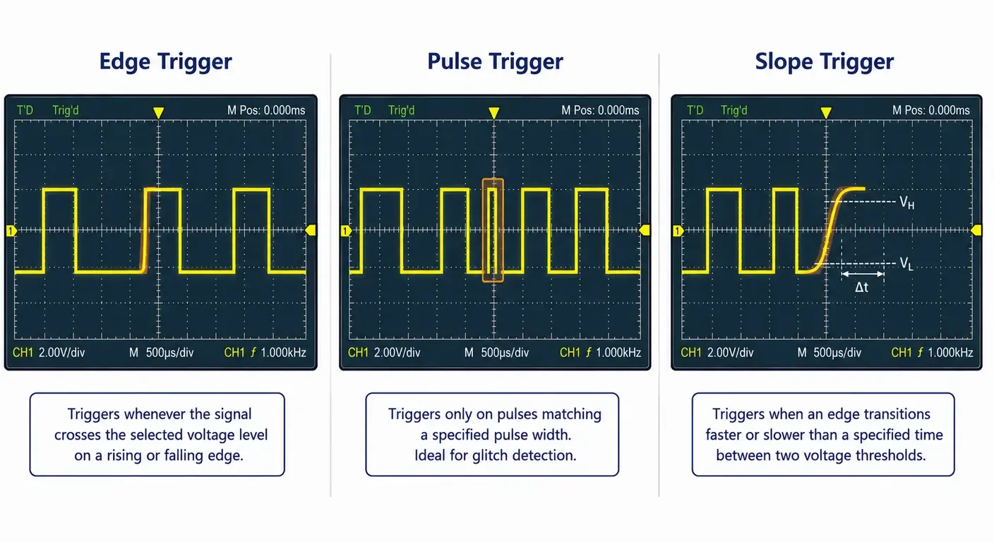
Edge triggering initiates waveform acquisition when the trigger source crosses a specified voltage threshold in a specified direction. It is the default trigger type on essentially every oscilloscope and is sufficient for the large majority of measurements.
Rising edge
A rising-edge trigger fires when the signal crosses the trigger level going from a lower voltage to a higher one. It is the natural choice when the event of interest begins with a transition to the active state — a clock edge, the start of a pulse, or the leading edge of a PWM cycle.
Falling edge
A falling-edge trigger fires on the downward crossing. It suits active-low signals, chip-select and reset lines, and any situation where the meaningful reference is the end of a pulse rather than its start.
Selecting the correct trigger level
Set the level where the signal has the steepest slope and the least noise, which for most digital and square-wave signals means roughly halfway between the low and high states.
Two effects push in this direction. First, timing uncertainty on the displayed waveform is proportional to noise amplitude divided by slew rate, so triggering on the fastest part of the edge minimizes trigger jitter. Second, thresholds placed close to the flat portions of the waveform sit inside the noise band, where random crossings can produce false triggers.
Trigger jitter is the acquisition-to-acquisition variation in the position of the trigger point relative to the actual signal edge. On screen it appears as horizontal blurring that grows with distance from the trigger point, since any timing error is displayed cumulatively across the record. The mechanism is direct: noise superimposed on the trigger source displaces the instant at which the signal crosses the threshold, and the resulting timing error is approximately the noise amplitude divided by the slew rate at the crossing point. The same noise therefore produces substantially more jitter on a slow edge than on a fast one, which is why a trigger level placed on the steepest part of the transition gives the most stable display. Instrument contributions exist as well, including trigger comparator noise and the resolution of the trigger interpolator, but on typical bench measurements noise on the signal itself usually dominates.
Common mistakes
- Setting the trigger level outside the signal’s amplitude range.
- Leaving the trigger source on a channel other than the one being probed.
- Using AC trigger coupling on a slowly repeating signal, where the coupling network attenuates the low-frequency content the trigger needs.
- Leaving the instrument in Auto mode and interpreting a forced, unsynchronized trace as a genuine measurement.
- Triggering on a noisy, heavily loaded node when a clean clock or sync line is available nearby.
Common Oscilloscope Trigger Types
Beyond edge triggering, oscilloscopes provide trigger types designed to isolate conditions that a simple threshold crossing cannot distinguish. Availability varies by instrument and class.
| Trigger Type | Best For | Typical Use |
|---|---|---|
| Edge | General measurements | Square waves, clocks |
| Pulse | Pulse width qualification | Glitch detection |
| Slope | Slow or fast edges | Signal integrity |
| Video | Composite video | Legacy video systems |
| Pattern | Logic combinations | Digital debugging |
Edge Trigger
The baseline trigger type, defined by source, level and slope. Use it first. If a measurement can be stabilized with an edge trigger, an advanced trigger adds configuration effort without adding information.
Pulse Trigger
A pulse trigger, also called pulse width trigger, qualifies on the duration of a pulse rather than on a single edge. Typical conditions include pulse width less than a value, greater than a value, or inside or outside a specified range.
This is the standard method for glitch detection. A narrow spurious pulse on a data line has the same amplitude as valid data and is indistinguishable to an edge trigger, but it can be isolated immediately by triggering on pulses narrower than the shortest legitimate pulse in the system. The same mechanism identifies missing or stretched pulses in a pulse train.
A practical example makes the difference clear. Suppose a microcontroller output normally produces pulses of 500 ns, but a marginal timing path occasionally generates a 100 ns glitch. An edge trigger fires on every pulse without distinction, so the anomaly is buried among thousands of correct ones and may never appear on screen. Configuring a pulse width trigger to accept only pulses narrower than roughly 200 ns causes the oscilloscope to ignore normal traffic entirely and acquire only the anomalies. Combined with Single mode, the fault is captured the first time it occurs, and the acquisition can then be used for measuring pulse width and characterizing the defect.
| Edge Trigger | Pulse Trigger |
|---|---|
| Triggers on voltage crossing | Triggers on pulse duration |
| Fast to configure | More selective |
| Ideal for repetitive signals | Ideal for glitches |
| Default trigger | Advanced trigger |
Video Trigger
A video trigger synchronizes to the sync structure of composite video signals, allowing acquisition on a specific line, on odd or even fields, or on all lines. Instruments that offer it typically support NTSC, PAL and SECAM, and some also handle progressive and high-definition formats.
Composite video is largely legacy in new designs, but the trigger remains relevant for service work, broadcast infrastructure, and analog camera or display systems still in the field.
Slope Trigger
A slope trigger — also described as a rise time or transition time trigger — fires when a signal takes more or less than a specified time to transition between two voltage thresholds. Rather than asking whether an edge occurred, it asks how fast.
It is useful for detecting slew rate degradation caused by excessive capacitive loading, weak drivers or damaged termination, and for isolating slow edges in a system where most edges are fast. Because the measurement depends on the instrument reproducing the transition faithfully, results are only meaningful when the oscilloscope bandwidth and the probe are adequate for the edge rate involved; the underlying failure mechanisms are covered in our introduction to signal integrity basics, and the associated technique in measuring rise time.
Pattern and advanced triggers (overview only)
Higher-specification instruments add trigger types that combine multiple conditions or multiple channels:
- Pattern triggers, which fire on a defined logic combination across several channels.
- Serial bus triggers, which fire on specific addresses, data values or error conditions on I²C, SPI, UART, CAN and similar protocols.
- Runt triggers, for pulses that cross one threshold but not the next.
- Setup and hold triggers, for timing violations between data and clock.
- Timeout triggers, for signals that remain in one state longer than expected.
- Window triggers, which fire when a signal enters or leaves a voltage band defined by an upper and a lower threshold.
Mid-range and high-end oscilloscopes generally provide most of this set — pattern, window, timeout, runt, setup and hold, and serial protocol triggering — either as standard functions or as licensed options. Entry-level instruments typically offer edge, pulse and video triggering, with the remainder appearing as the instrument class rises. The distinction matters when selecting an oscilloscope for digital debugging, since a trigger type that is absent cannot be substituted by post-processing an acquisition that was never captured.
These are covered in depth elsewhere; the point here is simply that they exist and that they extend the same principle — define a condition, acquire when it occurs.
What Is Trigger Holdoff?
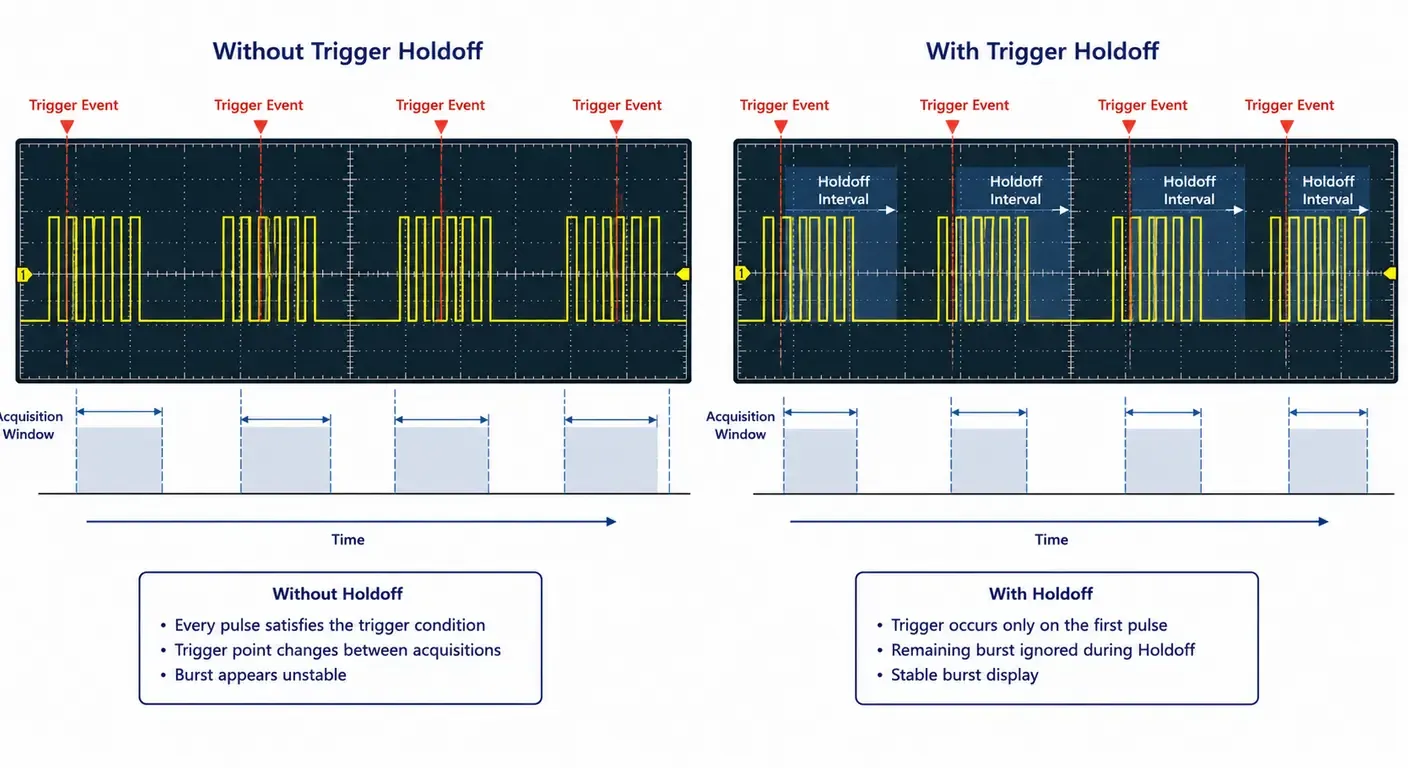
Trigger holdoff is a defined time interval after a trigger event during which the oscilloscope will not accept another trigger. It stabilizes signals that contain several qualifying edges within one repetition period, ensuring that acquisition always begins at the same point in the overall pattern.
Purpose
Edge triggering assumes that the chosen condition occurs once per repetition of the waveform. Many real signals violate that assumption: bursts, packets, modulated carriers and complex repeating patterns all contain multiple edges that satisfy the same trigger criterion.
When that happens, the oscilloscope triggers on whichever qualifying edge comes first after it rearms. Successive acquisitions start at different points in the pattern and the display appears to jump between several superimposed versions of the same signal.
How it works
After a valid trigger, the trigger circuit is disabled for the holdoff time. Once that interval expires, the circuit rearms and the next qualifying edge produces a trigger event.
By choosing a holdoff longer than the internal structure of the pattern but shorter than its repetition interval, you force the instrument to skip the intermediate edges and trigger consistently on the first one of each repetition. Holdoff is time-based on most instruments; some also offer holdoff by event count.
Example using pulse bursts
Consider a burst of eight pulses spaced 5 µs apart, with the burst repeating every 2 ms. The burst itself occupies roughly 40 µs.
With a plain rising-edge trigger, all eight pulses satisfy the condition, and the display alternates between eight different alignments of the same burst. Setting the holdoff to a value comfortably longer than the burst duration but well short of the repetition interval — 200 µs works here — causes the oscilloscope to trigger on the first pulse, ignore the remaining seven, and rearm during the idle period before the next burst. The result is a burst signal that is stationary on screen and can be measured.
Practical Triggering Examples
Square wave
For a 1 kHz square wave from a signal generator, set the trigger source to the probed channel, coupling to DC, slope to rising, and the trigger level to 50% of the amplitude. Begin in Auto mode to confirm the signal is present and correctly scaled, then switch to Normal so that any loss of the trigger condition is immediately visible rather than masked by forced acquisitions.
PWM signal
A PWM output has a constant period but a varying pulse width. A rising-edge trigger holds the leading edge stationary while the trailing edge moves with duty cycle, which is exactly what you want when observing modulation behavior.
To examine one specific operating condition instead, use a pulse width trigger set to the duration of interest. When the controller provides a sync or carrier clock output, triggering on that reference gives the most stable display of all. Related measurement technique is covered in our guide to measuring duty cycle with an oscilloscope.
Pulse train
For a continuous pulse train of identical pulses, an edge trigger is sufficient. When the train is organized into groups or frames, add holdoff as described above, or use an Nth-edge trigger if the instrument provides one.
Capturing rare events
For a startup transient, arm the oscilloscope in Single mode before applying power. Place the trigger point early in the record — for example at 10% of the horizontal span — so that most of the acquisition memory is allocated to what follows the event, while still preserving a short pre-trigger view of the initial conditions.
For an intermittent fault of unknown timing, combine Single mode with a qualifying trigger: a pulse width trigger for glitches, or a level threshold set outside the normal operating range for overshoot and undershoot. Adequate record length matters here as well, since the useful capture window is set by memory depth and sample rate together.
Troubleshooting Trigger Problems
Display won’t stabilize
Work through the settings in order: is the trigger source the channel actually being probed; is the trigger level inside the signal amplitude; is the mode appropriate; is holdoff set to a value left over from a previous measurement. If all four are correct and the display still moves, the signal may not be genuinely repetitive, in which case Single mode or a qualifying trigger is more appropriate than an edge trigger.
Incorrect trigger level
The symptom depends on mode. In Auto mode, an unreachable trigger level produces a continuously free-running, unsynchronized trace. In Normal mode it produces a frozen or blank screen. Both are frequently misread as instrument faults. Use the automatic 50% level function as a fast diagnostic: if the display stabilizes immediately, the level was the problem.
Noise causing false triggering
Noise superimposed on the trigger source can cross the threshold repeatedly, producing multiple trigger events per edge and a jittery display. Remedies, roughly in order of preference:
- Enable noise reject, which increases trigger hysteresis so that small excursions are ignored.
- Use HF reject coupling to attenuate high-frequency noise ahead of the trigger comparator, or LF reject to remove low-frequency drift and line-frequency pickup.
- Reduce pickup at the source by shortening the probe ground lead and probing closer to the reference point, as described in our oscilloscope probes guide.
Trigger coupling affects only the trigger circuit, not the displayed waveform, so these settings change stability without altering the measurement.
Wrong trigger source
Triggering on channel 1 while probing channel 2 is one of the most common configuration errors, closely followed by an external trigger input selected with nothing connected to it, and AC line triggering left enabled from an earlier power measurement. Confirm the source before changing anything else.
Beginner Trigger Setup Workflow
The following sequence resolves the majority of triggering problems without requiring any knowledge of the signal in advance. Work through it in order and stop as soon as the display is stable.
- Connect the probe. Attach the ground lead as close to the measurement reference as practical, and confirm probe compensation before relying on the displayed edges.
- Select the correct trigger source. Set it to the channel actually being probed, or to a clock or sync line if one is available.
- Choose Edge Trigger. Start with the simplest trigger type and only move to a qualifying trigger if the edge trigger cannot isolate the event.
- Use Auto mode. A forced acquisition guarantees that something appears on screen, which lets you set vertical and horizontal scaling before worrying about synchronization.
- Place the trigger level near 50%. Use the automatic 50% function if the instrument provides one; otherwise position the level marker visibly between the signal’s extremes.
- Verify waveform stability. A waveform that is now stationary confirms that the trigger condition is being met on every repetition.
- Switch to Normal mode if needed. This removes forced acquisitions, so any subsequent loss of trigger becomes immediately visible instead of being masked.
- Adjust holdoff only if required. Apply holdoff when the display still jumps between several alignments of the same pattern, and leave it at minimum otherwise.
Best Practices
Choose the right trigger mode
Use Auto for initial setup and unknown signals, Normal for routine measurement of repetitive waveforms, and Single for transients and one-time events. Leaving an instrument permanently in Auto mode hides trigger failures behind forced acquisitions.
Adjust trigger level
Place the level near the midpoint of the signal amplitude, where slew rate is highest and trigger jitter is lowest. Verify that the level marker sits visibly between the signal’s extremes on screen.
Use holdoff appropriately
Apply holdoff only when a repetition period contains multiple qualifying edges. Set it longer than the internal pattern structure and shorter than the repetition interval, and reset it to minimum when moving to a different signal.
Reduce trigger noise
Trigger on the cleanest available signal, use noise reject or HF reject when the source is inherently noisy, and treat poor probe grounding as a likely cause before assuming the instrument is at fault.
A trigger setting is not a display preference; it defines which portion of the signal the oscilloscope records and which portion it discards. Configuring it deliberately is part of the measurement, not a step that precedes it.
Nearly every bench measurement is governed by the same four decisions: which signal the instrument watches, at what voltage, in which direction, and what it does while waiting. Trigger source, trigger level, trigger slope and trigger mode together determine where the event of interest sits within the acquisition record, and correcting one of them resolves the overwhelming majority of unstable displays.
Advanced triggering earns its place only once those fundamentals are secure. Pulse, slope, window and protocol triggers are not substitutes for a correct source or a sensible level; they exist to isolate conditions that a threshold crossing cannot express, and the additional configuration effort is justified only when the simpler approach has demonstrably fallen short.
Triggering also depends on the rest of the instrument’s specification, since a correctly triggered event still has to be resolved once captured. Our guides to sample rate, bandwidth, memory depth and probes cover the parameters that determine how much of that event survives the measurement path.
Frequently Asked Questions
What is oscilloscope triggering?
Triggering is the process of starting a waveform acquisition when the input signal meets a defined condition, such as crossing a set voltage on a rising edge. Referencing every acquisition to the same signal event aligns successive traces, producing a stable display of a repetitive waveform instead of a moving one.
Why is my oscilloscope waveform unstable?
In most cases the trigger condition is not being met consistently. Check that the trigger source matches the probed channel, that the trigger level falls within the signal amplitude, and that holdoff is not set to an inappropriate value. A display that free-runs in Auto mode usually indicates the trigger condition never occurs.
What is edge triggering?
Edge triggering starts waveform acquisition when the trigger source crosses a specified voltage threshold on either a rising or falling edge. It is defined by three settings — source, level and slope — and is the default trigger type on virtually every oscilloscope, sufficient for most measurements.
What is pulse triggering?
A pulse trigger qualifies on pulse duration rather than on a single edge, firing when a pulse is narrower than, wider than, or within a specified width range. It is the standard method for glitch detection, since a narrow spurious pulse cannot be distinguished from valid data by an edge trigger alone.
What is trigger holdoff?
Trigger holdoff is a time interval after a trigger event during which the oscilloscope refuses further triggers. Setting it longer than the internal structure of a pattern but shorter than the pattern's repetition interval forces consistent triggering on the same point of each repetition, which stabilizes bursts and complex signals.
What is the difference between Auto and Normal trigger mode?
In Auto mode the oscilloscope forces an acquisition if no valid trigger occurs within a timeout, so something is always displayed even when unsynchronized. In Normal mode it updates only on a valid trigger, holding the previous acquisition otherwise. Auto suits setup and unknown signals; Normal suits infrequent or irregular signals.
What trigger level should I use?
Start at approximately 50% of the signal amplitude, where slew rate is highest and trigger jitter is lowest. Most oscilloscopes provide an automatic 50% function for this. Avoid levels close to the flat portions of the waveform, where noise can cause repeated threshold crossings and false triggers.
Why won't my oscilloscope trigger?
The most frequent causes are a trigger level outside the signal amplitude, a trigger source set to a channel that is not being probed, an external trigger input selected with nothing connected, or a signal that is not repetitive enough for the selected mode. Verify source and level first.
When should Single trigger mode be used?
Use Single mode for events that do not repeat: power-up transients, fault conditions, one-time glitches or manually initiated events. The instrument arms, captures one acquisition when the condition occurs, then stops and holds the result so it can be measured without being overwritten.
What is trigger slope?
Trigger slope defines the direction in which the signal must cross the trigger level: rising for a positive-going transition, falling for a negative-going one. Some instruments also allow either direction. Slope selection determines which signal edge appears at the trigger point and therefore what is displayed around it.
Can noise affect triggering?
Yes. Noise on the trigger source can cross the threshold repeatedly, generating multiple trigger events per edge and producing a jittery display. Noise reject increases trigger hysteresis, while HF reject and LF reject coupling attenuate unwanted frequency content ahead of the trigger circuit. Improving probe grounding addresses the cause directly.
What is the trigger source?
The trigger source is the signal the trigger circuit examines, typically an input channel but also an external trigger input, the AC line, or a digital channel on a mixed-signal instrument. It need not be the signal under measurement — a clock or sync line often provides a more reliable reference.
Can an oscilloscope trigger on one signal while displaying another?
Yes. On most oscilloscopes the trigger source is selected independently of the channels being displayed, and on many instruments a channel can act as the trigger source even when its trace is switched off. This is particularly useful when a clock, sync or enable line is cleaner and more regular than the signal under analysis: the instrument locks to the stable reference while the irregular waveform of interest is displayed in a fixed time relationship to it.
Related articles
Electronics18 min read
Function Generator vs Arbitrary Waveform Generator: What You Are Buying
Three names, two architectures: how DDS and point-by-point playback differ, what the labels hide, and how to read the architecture off a datasheet.
Electronics23 min read
How to Choose a Signal Generator: Getting the Signal You Asked For
How to turn a required stimulus into datasheet requirements: the load the instrument assumes, bandwidth against sample rate, reconstruction and vertical resolution.
Electronics22 min read
How to Choose a Multimeter: A Specification-Led Buying Guide
Choose a multimeter by the errors it introduces: burden voltage, input loading, AC bandwidth, safety category and accuracy on the reading you actually take.
Electronics16 min read
How to Use a Thermal Camera: Getting Readings You Can Trust
A thermal camera always shows a number. Learn the checks — emissivity, reflected temperature, focus and spot size — that decide whether it is a measurement.